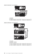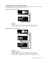
Cabling
the
Model
D20
to
a
pSeries
630
Model
6C4
The
Model
D20
subsystem
can
be
installed
in
any
location
in
a
standard
19-inch
EIA
rack.
The
cables
that
connect
the
subsystems
allow
some
flexibility
in
drawer
placement.
Up
to
two
Model
D20s
can
be
connected
to
a
pSeries
630
Model
6C4.
Each
I/O
subsystem
is
connected
to
the
processor
subsystem
using
a
system
power
control
network
(SPCN)
cable
loop
and
a
remote
I/O
(RIO)
cable
loop.
One
SPCN
cable
loop
is
needed
to
connect
the
I/O
subsystems
to
one
processor
subsystem.
Before
connecting
the
RIO-2
and
SPCN
cables
to
the
model
D20,
do
the
following:
1.
Ensure
that
your
Model
6C4
is
running
the
latest
level
firmware.
Refer
to
the
″
Firmware
Updates
″
section
of
the
″
Using
the
Service
Processor
″
chapter
in
the
Eserver
pSeries
630
Model
6C4
and
Model
6E4Service
Guide
,
order
number
SA38-0604.
For
information
about
checking
or
upgrading
the
firmware
level
of
your
Model
6C4.
2.
After
ensuring
that
your
firmware
is
at
the
latest
level,
turn
off
the
power
and
disconnect
the
Model
6C4
power
cables
from
the
power
source.
3.
Attach
the
RIO-2
and
SPCN
cables.
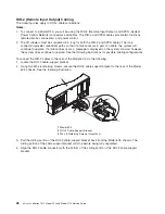
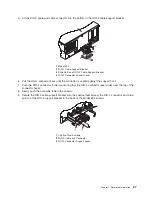
For
cabling
diagrams,
see
“RIO-2
(Remote
Input
Output)
Cabling”
on
page
26.
4.
After
connecting
the
RIO-2
and
SPCN
cables
from
the
Model
D20
to
your
system,
reconnect
the
system’s
power
cables
to
the
power
source
and
refer
to
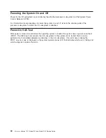
“Stopping
and
Starting
the
System”
on
page
42.
5.
Run
system
verification.
Refer
to
the
″
Verifying
the
Hardware
″
chapter
in
the
Eserver
pSeries
630
Model
6C4
and
Model
6E4
Installation
Guide
,
order
number
SA38-0604.
Your
Model
6C4
is
expandable
when
connected
up
to
two
Model
D20
I/O
drawers.
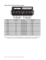
Each
Model
D20
can
contain
up
to
7
I/O
PCI
adapter
slots,
and
two
6-pack
disk
drive
(DASD)
bays.
Chapter
1.
Reference
Information
25
Summary of Contents for eserver pSeries 7311 D10
Page 1: ...pSeries 7311 Model D10 and Model D20 Service Guide SA38 0627 01 ERserver...
Page 2: ......
Page 3: ...pSeries 7311 Model D10 and Model D20 Service Guide SA38 0627 01 ERserver...
Page 8: ...vi Eserver pSeries 7311 Model D10 and Model D20 Service Guide...
Page 12: ...x Eserver pSeries 7311 Model D10 and Model D20 Service Guide...
Page 14: ...xii Eserver pSeries 7311 Model D10 and Model D20 Service Guide...
Page 25: ...1 Processor Subsystem 2 I O Subsystem Chapter 1 Reference Information 9...
Page 89: ...Chapter 3 Removal and Replacement Procedures 73...
Page 99: ...2 1 1 Top of Cassette 2 Handle Chapter 3 Removal and Replacement Procedures 83...
Page 179: ...D10 I O Subsystem Parts continued 1 2 3 4 5 6 7 Chapter 4 Parts Information 163...
Page 207: ......

