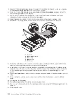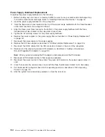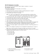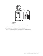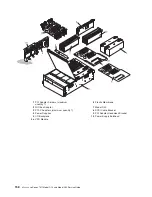
7.
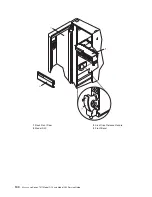
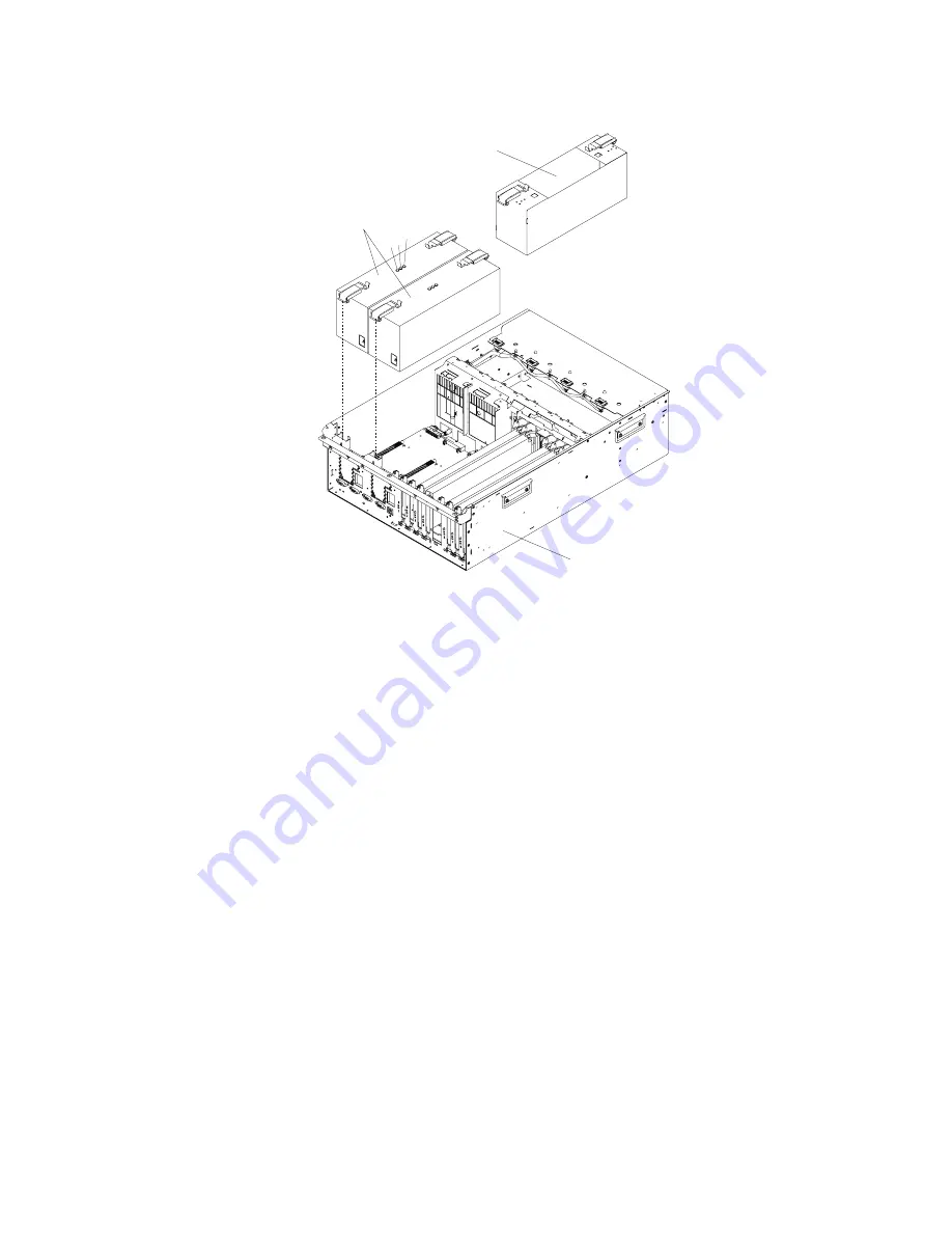
Carefully
remove
the
power
supply
from
the
subsystem.
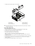
1
2 3 4
6
5
1
Power
Supplies
4
Green
DC
Good
LED
2
Green
Power
LED
5
Power
Supply
Filler
3
Amber
Fault/Identify
LED
6
Model
D20
Subsystem
Note:
During
normal
operation,
each
power-supply
bay
must
have
either
a
power
supply
or
filler
panel
installed
for
proper
cooling.
Power
Supply
Replacement
To
replace
a
power
supply,
do
the
following:
1.
Ensure
the
handles
are
in
the
unlocked
position
and
perpendicular
to
the
power
supply.
2.
Carefully
insert
the
new
power
supply
into
the
power
supply
bay.
3.
Press
the
power
supply
onto
the
docking
connectors.
4.
Put
the
power
supply
handles
into
the
locked
position.
Note:
The
handles
act
as
a
cam
and
will
correctly
seat
the
power
supply.
5.
Reconnect
the
power
source
to
the
replaced
power
supply.
The
green
LED
located
on
the
power
supply
comes
on
solid.
6.
Close
and
then
secure
the
service
access
cover
with
the
three
thumbscrews
located
on
its
back
edge.
7.
Put
the
Model
D20
subsystem
back
into
the
operating
position
as
described
in
“D20
Operating
Position”
on
page
114.
8.
If
your
system
has
successfully
powered
on,
close
the
rack
doors.
Chapter
3.
Removal
and
Replacement
Procedures
151
Summary of Contents for eserver pSeries 7311 D10
Page 1: ...pSeries 7311 Model D10 and Model D20 Service Guide SA38 0627 01 ERserver...
Page 2: ......
Page 3: ...pSeries 7311 Model D10 and Model D20 Service Guide SA38 0627 01 ERserver...
Page 8: ...vi Eserver pSeries 7311 Model D10 and Model D20 Service Guide...
Page 12: ...x Eserver pSeries 7311 Model D10 and Model D20 Service Guide...
Page 14: ...xii Eserver pSeries 7311 Model D10 and Model D20 Service Guide...
Page 25: ...1 Processor Subsystem 2 I O Subsystem Chapter 1 Reference Information 9...
Page 89: ...Chapter 3 Removal and Replacement Procedures 73...
Page 99: ...2 1 1 Top of Cassette 2 Handle Chapter 3 Removal and Replacement Procedures 83...
Page 179: ...D10 I O Subsystem Parts continued 1 2 3 4 5 6 7 Chapter 4 Parts Information 163...
Page 207: ......

