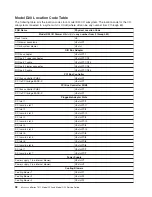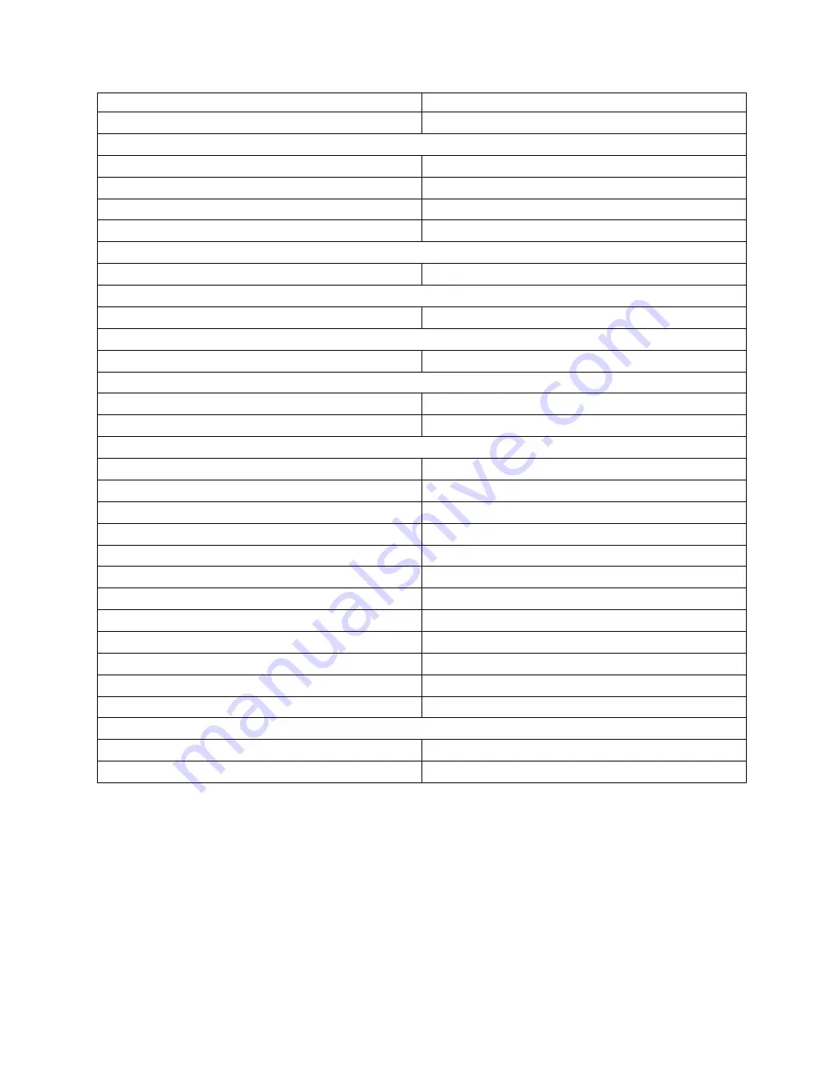
FRU
Name
Physical
Location
Code
Cooling
blower
4
U0.
dd
-F4
SPCN
Connectors
SPCN
connector
1
U0.
dd
-P1/Q3
SPCN
connector
2
U0.
dd
-P1/Q4
SPCN
connector
3
U0.
dd
-P1/Q5
SPCN
connector
4
U0.
dd
-P1/Q6
Rack
Indicator
Rack
beacon
(4–pin)
U0.
dd
-P1/Q7
Operator
Panel
Operator
panel
U0.
dd
-L1
Temperature
Sensor
Temperature
sensor
(on
operator
panel)
U0.
dd
-L1
Disk
Drives
Backplanes
Disk
drives
backplane
1
U0.
dd
-P3
Disk
drives
backplane
2
U0.
dd
-P4
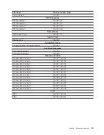
Disk
Drive
Locations
Hot-swap
disk
drive
bay
1
U0.
dd
-P1-Ix/Zn-A8
Hot-swap
disk
drive
bay
2
U0.
dd
-P1-Ix/Zn-A9
Hot-swap
disk
drive
bay
3
U0.
dd
-P1-Ix/Zn-AA
Hot-swap
disk
drive
bay
4
U0.
dd
-P1-Ix/Zn-AB
Hot-swap
disk
drive
bay
5
U0.
dd
-P1-Ix/Zn-AC
Hot-swap
disk
drive
bay
6
U0.
dd
-P1-Ix/Zn-AD
Hot-swap
disk
drive
bay
7
U0.
dd
-P1-Iy/Zn-A8
Hot-swap
disk
drive
bay
8
U0.
dd
-P1-Iy/Zn-A9
Hot-swap
disk
drive
bay
9
U0.
dd
-P1-Iy/Zn-AA
Hot-swap
disk
drive
bay
10
U0.
dd
-P1-Iy/Zn-AB
Hot-swap
disk
drive
bay
11
U0.
dd
-P1-Iy/Zn-AC
Hot-swap
disk
drive
bay
12
U0.
dd
-P1-Iy/Zn-AD
SCSI
SES0
U0.
dd
-P1-Ix/Zn-AF
SES1
U0.
dd
-P1-Iy/Zn-AF
Chapter
1.
Reference
Information
33
Summary of Contents for eserver pSeries 7311 D10
Page 1: ...pSeries 7311 Model D10 and Model D20 Service Guide SA38 0627 01 ERserver...
Page 2: ......
Page 3: ...pSeries 7311 Model D10 and Model D20 Service Guide SA38 0627 01 ERserver...
Page 8: ...vi Eserver pSeries 7311 Model D10 and Model D20 Service Guide...
Page 12: ...x Eserver pSeries 7311 Model D10 and Model D20 Service Guide...
Page 14: ...xii Eserver pSeries 7311 Model D10 and Model D20 Service Guide...
Page 25: ...1 Processor Subsystem 2 I O Subsystem Chapter 1 Reference Information 9...
Page 89: ...Chapter 3 Removal and Replacement Procedures 73...
Page 99: ...2 1 1 Top of Cassette 2 Handle Chapter 3 Removal and Replacement Procedures 83...
Page 179: ...D10 I O Subsystem Parts continued 1 2 3 4 5 6 7 Chapter 4 Parts Information 163...
Page 207: ......


