background image

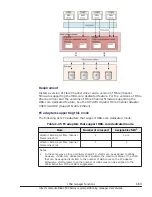
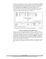
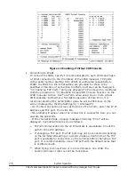
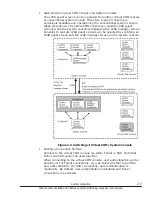
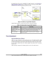
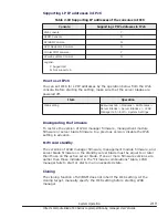
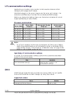
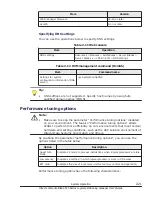
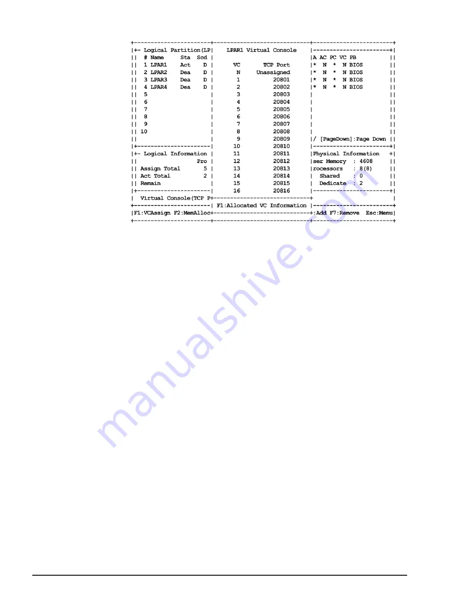
Figure 2-3 Enabling of Virtual COM Console

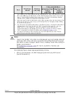
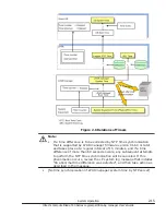
Connecting to LPARs
To connect to LPARs, specify TCP ports allocated to each LPAR and make

a Telnet connection to the IP address of the LPAR manager. TCP ports

with a serial number starting from 20801 are allocated sequentially to

LPAR1 to LPAR16 in the initial setting are provided for those to be

specified at the time of connection to LPARs, but they can be changed in

"(4) Changing TCP Ports." Currently allocated TCP ports can be monitored

with the procedure in "(1) Enabling Virtual COM Console Function on the

LPAR manager Screen. Use Tera Term when using one or more virtual

COM consoles. Furthermore, for stable operation of Tera Term, it is

recommended that the Scroll Buffer value be set to 2000 lines on the

screen displayed by clicking Settings(S) > Window(W).
– On the New Connection screen at the boot of Tera Term, enter the LP IP

Address and TCP port. Then click OK.
– OS prompt will appear when the connection is successful. Here you can

operate the guest OS.
– If the connection fails, a popup message informing "Error" will be

displayed. Connection failures are as follows:

¢

TCP/IP communication to the LP IP Address is unavailable. Check the

path to the LP IP Address.

¢

If changing a TCP port, the TCP port may not be connected depending

on the terminal OS setting or account privilege. Confirm that the TCP

port is available for connection on the terminal before changing a TCP

port. It is recommended to use a TCP port with the default value that

is verified enough.

¢

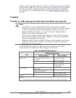
When trying to connect two or more terminals to one LPAR, the

second terminal or later cannot be connected.

2-6

System Operation

Hitachi Compute Blade 500 Series Logical partitioning manager User's Guide

Summary of Contents for CB 520A A1

Page 1: ...Hitachi Compute Blade 500 Series Logical partitioning manager User s Guide MK 91CB500068 27 Document Organization Product Version Getting Help Contents ...

Page 2: ...onditions of the applicable Hitachi Data Systems Corporation agreements The use of Hitachi Ltd products is governed by the terms of your agreements with Hitachi Data Systems Corporation Hitachi is a registered trademark of Hitachi Ltd in the United States and other countries Hitachi Data Systems is a registered trademark and service mark of Hitachi Ltd in the United States and other countries Arch...

Page 3: ...ynamically change 1 5 Service Ratio 1 6 Idle Detection 1 7 Processor Capping 1 8 Processor Group 1 9 Hyper Threading 1 10 PRTE 1 12 Logical Partitioning of Memory 1 13 Guest NUMA 1 15 L3 cache allocation functionality 1 18 Logical Partitioning of PCI Devices 1 19 NIC Network Interface Card 1 22 Management Path 1 32 SR IOV 1 40 FCoE 1 43 Port Multiple Assignment 1 44 Port Separate Assignment 1 44 T...

Page 4: ... DNS 2 20 Performance tuning options 2 21 3 High Reliability Functions 3 1 Redundancy 3 2 Redundancy of Power Supply 3 2 Redundancy of Management Module 3 2 Redundancy of LAN switch FC switch 3 3 RAID configuration and duplex controllers 3 3 N M Cold Standby 3 3 Microsoft Cluster Service Microsoft Failover Cluster 3 7 UPS 3 9 Role Based Access Control 3 11 User types 3 11 Role types 3 12 Assigning...

Page 5: ...ager firmware 4 14 LPAR Migration 4 16 Safe mode 4 17 5 Setup of LPAR manager 5 1 Setup Overview 5 2 Setup of Terminal Software 5 4 Connects LPAR manager Screen 5 6 LPAR manager Settings 5 7 Creating LPAR 5 10 Adding LPAR 5 10 Configuration of Processor 5 12 Configuration of Memory 5 16 Configuration of PCI Device 5 18 Assign VNICs Virtual NICs to LPARs 5 26 Assign Shared FCs to LPARs 5 28 Save Co...

Page 6: ...on 7 32 PCI Device Information 7 35 PCI Device Assignment 7 39 Virtual NIC Assignment 7 44 Shared FC Assignment 7 56 Allocated FC Information 7 61 System Configuration 7 63 System Service State 7 76 Date and Time 7 81 LP Options 7 105 LPAR Usage 7 118 Front Panel 7 124 LP system logs 7 128 Firmware Version Information 7 131 8 LPAR manager Dump Collection 8 1 Check the LPAR manager Dump 8 2 Collect...

Page 7: ...solation degradation for CPU memory or PCI device 10 14 CPU core degradation 10 14 Restrictions on use of Onboard LAN 10 14 Restrictions on use of Emulex 10Gb NIC 10 15 Restrictions of the numbers of NIC ports assignment for Windows 10 16 Multicast communication errors 10 18 Performance Slowdown on the Management Path 10 19 Expansion of VNIC System No 10 20 Remote Console Function 10 20 NETM Remot...

Page 8: ... Port numbers D 2 E System Configuration E 1 Recommended LPAR manager Configuration SAN Boot E 2 F HvmGetPerf Command F 1 HvmGetPerf Command F 2 G Software License Information G 1 Software License Information G 2 viii Hitachi Compute Blade 500 Series Logical partitioning manager User s Guide ...

Page 9: ...he preface Notice The use of Compute Blade 500 and all other Hitachi Data Systems products is governed by the terms of your agreement s with Hitachi Data Systems Intended Audience Product Version Release Notes Referenced Documents Document Organization Document conventions Convention for storage capacity values Getting help Comments Preface ix Hitachi Compute Blade 500 Series Logical partitioning ...

Page 10: ...er Blade Setup Guide Hitachi Compute Blade 500 Series Management Module Setup Guide Hitachi Compute Blade 500 Series Web Console User s Guide Hitachi Compute Blade 500 Series EFI User s Guide Hitachi Compute Blade Series Hitachi Compute Rack Series OS Installation Guide for Windows Server Hitachi Compute Blade Series OS Installation Guide for Red Hat Enterprise Linux Hitachi Compute Blade Emulex A...

Page 11: ...f LPAR manager Explains setup of LPAR manager by using the LPAR manager screen Contents on the screens might be changed depend on the version Chapter 6 LPAR manager backup Explains LPAR manager backup Chapter 7 Operation by LPAR manager Screen Explains LPAR manager operation by using the LPAR manager screen Chapter 8 LPAR manager Dump Collection Explain the over view of LPAR manager at this chapte...

Page 12: ...ser input angled brackets Variable used when italic is not enough to identify variable square bracket Optional values braces Required or expected value vertical bar Choice between two or more options or arguments This document uses the following icons to draw attention to information Icon Meaning Description WARNING This indicates the presence of a potential risk that might cause death or severe i...

Page 13: ...calculated based on the following values Logical capacity unit Value 1 block 512 bytes 1 KB 1 024 210 bytes 1 MB 1 024 KB or 1 0242 bytes 1 GB 1 024 MB or 1 0243 bytes 1 TB 1 024 GB or 1 0244 bytes 1 PB 1 024 TB or 1 0245 bytes 1 EB 1 024 PB or 1 0246 bytes Getting help The Hitachi Data Systems customer support staff is available 24 hours a day seven days a week If you need technical support log o...

Page 14: ...r to specific sections and paragraphs whenever possible All comments become the property of Hitachi Data Systems Corporation Thank you xiv Preface Hitachi Compute Blade 500 Series Logical partitioning manager User s Guide ...

Page 15: ...nager Overview Logical Partitioning Logical Partitioning of Processors Logical Partitioning of Memory Logical Partitioning of PCI Devices NIC Network Interface Card FC Fibre Channel USB KVM LPAR manager Functions 1 1 Hitachi Compute Blade 500 Series Logical partitioning manager User s Guide ...

Page 16: ...erating a server blade without partitioning is called the Basic mode Unless explicitly specified the terms physical and logical are used in this chapter as defined in the table below Table 1 1 Physical and Logical resources Term Description Physical Indicates the resources that actually exist in the system Physical is sometimes omitted except where this would cause confusion Logical Indicates the ...

Page 17: ... the LPAR that can use resources make sure to shut down the LPAR once to change the configuration definition Processors Memories PCI devices Shared Time shared The particular LPARs to which a hardware resource has been allocated timeshare the hardware resource LPAR manager keeps switching LPARs that can use the device at very short time intervals Processors PCI devices Exclusive shared One of the ...

Page 18: ...ocessors available System required high processing performance System required critical time period and high processing in performance Shared Mode Physical processors are time shared among the logical processors defined in the LPAR for which the shared mode is specified The utilization rate of the physical processors can be set dynamically for each LPAR allowing flexible use of physical processor ...

Page 19: ...hared and dedicated LPARs can be switched dynamically without deactivating a The Scheduling mode of arbitrary Logical processor can be changed from dedicated mode to shared mode b The Scheduling mode of arbitrary Logical processor can be changed from shared mode to dedicated mode LPAR manager Functions 1 5 Hitachi Compute Blade 500 Series Logical partitioning manager User s Guide ...

Page 20: ...e time with 10 millisecond time slice accuracy which equals 1 of a unit processor time 1 second Service ratio has a meaning only to LPAR of shared mode Service ratio does not have any meaning to LPAR of shared mode and cannot be assigned The examples of the relations between Service Ratio and allocation rate are as follows Example 1 This example shows the allocation rates of LPAR1 Service Ratio 10...

Page 21: ...is compensated so that the time in which a single logical processor uses the physical processor becomes 1 10 milliseconds of the unit processor time 1 second If the number of logical processors allocated to a single LPAR does not satisfy the assigned allocation rate the allocation rate is compensated to the one that is based on the number of logical processors Idle Detection A shared mode LPAR whi...

Page 22: ... tolerance of 1 for each unit of processor time a shared mode LPAR is allocated a maximum processor time that is 1 greater than the total service time of the physical processors assigned to it and may exceed the allocation rate Note that the processor capping function does not affect the execution of the dedicated mode LPARs Also processor capping has a meaning only to LPAR of shared mode Processo...

Page 23: ...d processor to being in a group It is possible to restrict in a group with effect of load fluctuating by above mentioned It is possible to define group by every user section and charge to an allocated processor performance Figure 1 10 Assignment of Processor Group Change Group Assignment of Processor Performance of processor group can be changed by changing group assignment of processors Definitio...

Page 24: ...hreading Total performance of the LPAR manager increases up to 20 by enabling Hyper Threading definition The LPAR manager performance is affected by processor assignment Table 1 4 Processor Assignment Mode Assignment Mode Processor Number Description LPAR1 LPAR2 Dedicated 2 Dedicated 4 Performance of LPARs not interfere each other Performance increases by assigning of even number processors 1 10 L...

Page 25: ...for File servers Web servers Dedicated 3 Dedicated 3 Not recommend LPAR performance is affected from load of other LPARs Dedicated 3 Dedicated 2 Not recommend LPAR performance is affected from load of other LPARs Dedicated 3 Dedicated 3 Not recommend LPAR performance is affected from load of other LPARs Assigned even number processors to LPAR with Dedicated mode Figure 1 13 Processor Assignment Mo...

Page 26: ...ng mode Figure 1 16 Processor Assignment Mode 4 Assigned odd number processors to LPAR with Shared Dedicated mixing mode Figure 1 17 Processor Assignment Mode 5 PRTE The PRTE function provides a timer that can be referred without intervention of the LPAR manager 1 12 LPAR manager Functions Hitachi Compute Blade 500 Series Logical partitioning manager User s Guide ...

Page 27: ...OSs Windows Server 2012 Windows Server 2012 R2 Method of setting the PRTE function You are able to change the setting of the PRTE function only for deactivated LPARs The method of setting the PRTE function is as follows 1 Connect to the LPAR manager screen and then display the Logical Partition Configuration screen 2 Use the F11 and F12 keys to scroll the page to the left and right Place the curso...

Page 28: ...l firmware uses a part of memory space assigned to each LPAR Memory that logical firmware uses in general can be estimated from the following calculation formulas Less than 8 GB memory assigned to LPAR 0 6 of memory assigned to LPAR number of logical processors x 2 25 MB 65 MB 8 GB or larger memory assigned to LPAR 0 25 of memory assigned to LPAR number of logical processors x 2 25 MB 80 MB Memory...

Page 29: ...binding for 02 40 or later Physical processor binding is the method for associating logical processors with physical processors Physical NUMA node binding is the method for associating logical processors with physical NUMA nodes The table below explains specific differences between these binding methods with regard to how to configure an LPAR Item Physical processor binding Physical NUMA node bind...

Page 30: ...ration Guide 5 Set the processor scheduling mode Set the processor scheduling mode to dedicated mode For details see Logical Partition Configuration on page 7 9 6 Specify the number of logical processors Specify the number of logical processors in the entire LPAR For details see Logical Partition Configuration on page 7 9 If you want to assign processors from multiple nodes you must ensure that ea...

Page 31: ...ode For details see Logical Partition Configuration on page 7 9 Notes on the guest NUMA Remember the following if you want to use the guest NUMA If you change the MM Config Base setting for EFI the memory size that can be allocated to each node changes For this reason activation of the LPAR for which a memory node is specified might fail due to insufficient memory on the target node If you change ...

Page 32: ...h LPAR but you can dynamically change the size of the L3 cache space that is allocated to each LAPR Note however that you can change the L3 cache allocation only for LPARs to which processors have been allocated in dedicated mode You can allocate L3 cache space to LPARs by using the capacity bit mask CBM format a mask value format By using a CBM you can specify not only the size of the L3 cache sp...

Page 33: ... details see the HVM Management Command HvmSh Operation Guide Enabling the L3 cache allocation functionality To enable the L3 cache allocation functionality 1 From the Web console enable Performance tuning options For details see Performance tuning options on page 2 21 2 Specify the L3 cache allocation settings by using the HVM management command HvmSh execute the opr LparCatCbm command For detail...

Page 34: ...assigned PCI device at the same time without knowing that the PCI device is shared with other OSs NIC performance of an LPAR is affected by I O load of other LPARs System required cost efficiency and flexibility rather than high processing performance System required balanced processing between LPARs Exclusive shared mode A single PCI device is assigned to a single LPAR guest OS PCI device assignm...

Page 35: ... a KVM device or a remote console are assigned to a LPAR by Exclusive Shared Mode however a USB device is assigned to a LPAR by Dedicated Mode Example of Exclusive Shared Mode is below Figure 1 22 PCI Device Assignment in Exclusive Shared Mode LPAR manager Functions 1 21 Hitachi Compute Blade 500 Series Logical partitioning manager User s Guide ...

Page 36: ...d NIC LPAR manager supports assigning of Dedicated NIC Shared NIC is useful for solving lack of hardware resources and increasing use efficiency of devices on the virtual environment Dedicated NIC brings high performance for communication without influences from other LPARs Shared NIC Network segments for shared NICs can be assigned when the NIC scheduling mode is set to shared mode NIC assigned t...

Page 37: ...Network segment Onboard LAN1 Emulex 10Gb 2ports 0 0 1 1a 1 1 1b Onboard LAN2 Emulex 10Gb 2ports 0 0 2 2a 1 1 2b Notes 1 The physical port number which exists on the system 2 The logical port number which displays on the LPAR manager screen Table 1 8 Example for CB 520H A1 B1 B2 B3 B4 when Onboard LAN Card is not installed Emulex 10Gb 4ports Physical NIC Physical Port No 1 Logical Port No 2 Detecti...

Page 38: ...Logical Port No 2 Detection No of LAN controller Network segment Mezzanine Card 1 Emulex 10Gb 4ports 0 0 1 1a 1 1 1b 2 2 2 2a 3 3 2b Mezzanine Card 3 Emulex 10Gb 4ports 3 0 0 3 3a 1 1 3b 2 2 4 4a 3 3 4b Notes 1 The physical port number which exists on the system 2 The logical port number which displays on the LPAR manager screen 3 NIC cannot be installed on Mezzanine Card 3 for CB 520X B1 Table 1 ...

Page 39: ...3 3 1d Notes 1 The physical port number which exists on the system 2 The logical port number which displays on the LPAR manager screen Table 1 13 Example for CB 540A A1 B1 CB 520X B1 B2 B3 when Onboard LAN Card is not installed Broadcom 1Gb 4ports Physical NIC Physical Port No 1 Logical Port No 2 Detection No of LAN controller Network segment Mezzanine Card 1 Broadcom 1Gb 4ports 0 0 1 1a 1 1 1b 2 ...

Page 40: ...7 7 2d Notes 1 The physical port number which exists on the system 2 The logical port number which displays on the LPAR manager screen Table 1 15 Example for CB 520A A1 when Onboard LAN Card is not installed Broadcom 1Gb 8ports Physical NIC Physical Port No 1 Logical Port No 2 Detection No of LAN controller Network segment Mezzanine Card 1 Broadcom 1Gb 8ports 0 0 1 1a 1 1 1b 2 2 1c 3 3 1d 4 4 2 2a...

Page 41: ... 0 1 1a 1 1 1b 2 2 1c 3 3 1d 4 4 2 2a 5 5 2b 6 6 2c 7 7 2d Mezzanine Card 3 Broadcom 1Gb 8ports 3 0 0 3 3a 1 1 3b 2 2 3c 3 3 3d 4 4 4 4a 5 5 4b 6 6 4c 7 7 4d Notes 1 The physical port number which exists on the system 2 The logical port number which displays on the LPAR manager screen 3 NIC cannot be installed on Mezzanine Card 3 for CB 520X B1 LPAR manager Functions 1 27 Hitachi Compute Blade 500...

Page 42: ...rent network segments an external network is used VF NIC A network segment of VF NIC can be set when SR IOV as a hardware function of physical NIC is available on LPAR manager and NIC scheduling mode is shared mode NIC assigned the network segments is called VF NIC VF NIC is set on the Virtual NIC Assignment screen For LPAR manager up to 8 physical LAN controllers can be assigned and up to 16 phys...

Page 43: ...twork segment Onboard LAN1 Emulex 10Gb 2ports 0 0 1 1av 1 1 1bv Onboard LAN2 Emulex 10Gb 2ports 0 0 2 2av 1 1 2bv Notes 1 The physical port number which exists on the system 2 The logical port number which displays on the LPAR manager screen Table 1 19 Example for CB 520H A1 B1 B2 B3 B4 when Onboard LAN Card is not installed Emulex 10Gb 4ports Physical NIC Physical Port No 1 Logical Port No 2 Dete...

Page 44: ...0A A1 B1 CB 520X B1 B2 B3 when Onboard LAN Card is not installed Emulex 10Gb 4ports Physical NIC Physical Port No 1 Logical Port No 2 Detection No of LAN controller Network segment Mezzanine Card 1 Emulex 10Gb 4ports 0 0 1 1av 1 1 1bv 2 2 2 2av 3 3 2bv Mezzanine Card 3 Emulex 10Gb 4ports 3 0 0 3 3av 1 1 3bv 2 2 4 4av 3 3 4bv Notes 1 The physical port number which exists on the system 2 The logical...

Page 45: ... same network segment does not use an external network In contrast communication between VF NICs connected to different network segments takes place over an external network Virtual NIC Up to 4 Network Segment for Virtual NIC can be defined on an LPAR manager NIC assigned the network segments is called Virtual NIC Virtual NIC can communicate through no physical NIC network between LPARs LPAR manag...

Page 46: ...Segment cannot communicate each other Management Path The network path configured for server operation is called operation path The network path configured for management and operation of server and LPAR manager is called management path Before starting LPAR manager you must configure a management path to be used for communication between LPAR manager and the management module The scheduling mode ...

Page 47: ...en if the primary management path recovers when the secondary management path works A redundant configuration is maintained after recovery of the primary management path You can also specify only one port as the management path In this case the management path is non redundant If you do not specify the management path the port 0 and port 1 which are 1a and 1b in the virtual network segment of the ...

Page 48: ...r blades are powered off Table 1 23 Web Console Item Operation Management path setting Resources tab Modules All Modules Server Blades Server Blades x LPAR Manager tab Edit System Settings The scheduling mode of the NIC that is used as the management path The initial value of the scheduling mode of the NIC that is used as the management path is the shared mode therefore you can use the NIC as the ...

Page 49: ...FF40 Warning The scheduling mode for a NIC assigned to an LPAR was changed 0xFF41 error An error event on a management NIC was detected 0xFF42 Warning A warning event on a management NIC was detected 0xFF43 Information LP started with the specified ports set as the LP management NIC ports 0xFF44 error An error event occurred on the management NIC port 0xFF45 Warning A warning event occurred on the...

Page 50: ...manager fails to start or starts in an unexpected state For details on the firmware combinations see Firmware combinations on page 1 34 Cloning The cloning function of SC BSM does not inherit the setting of ports used as the management path At the cloning target manually set the ports before booting LPAR manager The status of the management path Displays the state of the management path In additio...

Page 51: ... To diagnose the communication state periodically enable management path periodical diagnosis You can display the current status by the following operations Table 1 30 Web Console Item Operation Manual management path diagnosis Resources tab Modules All Modules Server Blades Server Blades x LPAR Manager tab Edit LP options Periodical management path diagnosis Resources tab Modules All Modules Serv...

Page 52: ...in communication with a management module by performing the following outputs LP System Log Communication is disabled when LP detected error of network communication for SVP access is displayed After that communication is recovered when LP detected recovery of network communication at SVP access is displayed System Event Log SEL Communication is disabled when Communication Failure between LP and M...

Page 53: ...NICs for the management LAN and the operation LAN The example of configuration shows as follows VLAN settings for the management path and operation path Guest OS LPAR manager Internal LAN switch VLAN None management path VLAN None operation path Not configured 1 VLAN None 2 Access port settings VLAN ID 100 Note Do not set the VLAN configuration on OS or LPAR manager for the management path When us...

Page 54: ...iew LPAR manager supports SR IOV which is hardware functionality of a physical NIC You can use VF NICs by enabling SR IOV and setting the NIC scheduling mode to shared mode The features of SR IOV are as follows Capable of transferring data at a high speed comparable to dedicated NICs The load on the physical processor is low compared to a shared or virtual NIC Transmission bandwidth limitations ca...

Page 55: ...te Guide Note that in LP mode you cannot update NIC firmware Change to Basic mode before updating NIC firmware Set up SR IOV For details about setting up SR IOV see the Hitachi Compute Blade Emulex Adapter User s Guide for Hardware Note that in LP mode you cannot set up SR IOV Change to Basic mode before setting up SR IOV Set shared mode On the PCI Device Assignment screen for LPAR manager set the...

Page 56: ...aming interface see the following Configuring a teaming interface a Boot a guest OS to which VF NIC ports assigned with the original MAC address set for each of the VF NIC ports to be set in a team Note that when you remove a teaming interface you need to reset the original MAC address for each of the VF NIC ports We recommend that you take a note of the original MAC addresses b Confirm that each ...

Page 57: ...guest OS is not affected be2net 0000 XX XX X VF is not privileged to issue opcode 125 1 XX XX X Bus Dev Func FCoE Overview To perform an FCoE boot which is hardware functionality of a physical NIC enable FCoE Supported specifications The following is the supported specifications The FCoE functionality is supported only by onboard LANs Emulex XE104 If the FCoE functionality is enabled the SR IOV fu...

Page 58: ...tion makes it possible to assign multiple ports of physical NIC the target LPAR The function is efficient especially when small number of NIC cards are installed because the number of segments more than the number of physical NICs can be assigned Figure 1 26 Port Multiple Assignment of Logical NIC Port Separate Assignment Logical NIC is also supporting the Port Separate Assignment function Port Se...

Page 59: ...e TagVLAN function which is based on the IEEE 802 1Q Flexible network environment can be built by using the TagVLAN function Multiple broadcast domain can be built by using only a physical NIC Multiple VLAN ID can be assigned to Logical NIC Network interface between physical NIC and network switch uses the tag whose form is the IEEE 802 1Q LPAR manager Functions 1 45 Hitachi Compute Blade 500 Seri...

Page 60: ... is specified only one VLAN ID can be specified Tagged Port With this setting a NIC receives frames containing IEEE 802 1Q format tags and untagged frames that include any of the specified VLAN IDs A Logical NIC for which tagged port is specified can receive both tagged frames with the specified VLAN ID and untagged frames Tagged frames sent from a Logical NIC with the tagged port specification ar...

Page 61: ...r the port receives the frame Filtering the receiving frames is described in the table below Table 1 33 Tagged VLAN Mode for Receiving VLAN mode of receiving ports Receiving Frame Untagged Tagged VLAN ID Tagged VLAN ID Undef Accept Reject Reject Tagged Accept Accept Reject Untagged Accept Adding Tags Reject Reject Sending Frames MAC address table selects ports for transfer among ports in which con...

Page 62: ...packets received by the Logical NIC This means that the guest OS will not be aware of the VLAN so you can divide the broadcast domain for each Logical NIC Assign one Logical NIC to multiple broadcast domains within the same virtual network By making VLAN settings for the Logical NIC from the guest OS you can use the functions equivalent to the physical NIC to operate tags and perform frame filteri...

Page 63: ...When sending receiving Untagged packets to from the external switch without setting TagVLAN on OS Set the Undef mode to the corresponding port on the Virtual NIC VNIC Assignment screen of LPAR manager Virtual Switch Image The following describes the image of Virtual Switch Image of Virtual NIC switch The following example is for 128 ports 8 ports LPAR layer 2 switch when the number of LPARs is 16 ...

Page 64: ...sign all ID Untagged Only one 1 VLAN ID out of the range from 1 to 4094 Port mirroring Port1 Port128 If promiscuous mode is Restricted Receives only the packets to the target LPARs MAC addresses If promiscuous mode is Through default Receives all the packets in the same network segment Jumbo frame function Port1 Port128 Always enabled Uplink failover Port1 Port128 Always disabled The ports are alw...

Page 65: ...Assignment screen Port17 Connect to physical cables With the Onboard NIC no cable is required Port Speed Port1 Port16 Auto Negotiation This setting cannot be changed Supports 1000BASE TX Port17 Auto Negotiation This setting cannot be changed Supports 10 100 1000 10000BASE TX VLAN Port1 Port16 VLAN mode Undef Default Tagged Untagged Only 1 VLAN mode can be set per LPAR VLAN ID Tagged Up to 16 VLAN ...

Page 66: ...bled IGMP Snooping Port1 Port17 Always disabled Spanning tree Port1 Port17 Always disabled Image of VF NIC switch The following example is for 17 ports 1 port LPAR layer 2 switch when the number of LPARs is 16 and 1 VF NIC per LPAR Up to 16 pieces of this switch can be mounted depending on the number of physical NICs with shared setting Ports 1 16 are configured by the VF NICs and Port17 by the ph...

Page 67: ...agged All This setting cannot be changed Configured to transmit all packets Port mirroring Port1 Port17 If promiscuous mode is Restricted default Receives only the packets to the target LPARs MAC addresses Through Not supported Jumbo frame function Port1 Port17 Always enabled Maximum value 9000 bytes Uplink failover Port1 Port17 Always enabled If Port 17 is linked down all the other ports from Por...

Page 68: ...to the shared physical NIC to physical switch port at the tagged port Priority control in the IEEE802 1P format Priority control in the IEEE802 1P format is not supported When using VLAN functions and N M cold standby at the same time attentions are as follows Table 1 38 The attentions when using VLAN functions and N M cold standby at the same time Switch Description LAN Switch Cooperation with Cm...

Page 69: ...lb Y N balance alb Y N Legend Y Can be used N Cannot be used Not supported Teaming image by using Logical NIC is below Figure 1 33 Teaming Function on the LPAR manager Promiscuous Mode Shared NIC and virtual NIC support Promiscuous mode That mode can be configured with Virtual NIC Assignment screen LPAR manager Functions 1 55 Hitachi Compute Blade 500 Series Logical partitioning manager User s Gui...

Page 70: ...nvironment When Promiscuous mode is Restricted Case1 Bridge function has been installed to the guest OS LPAR cannot transfer any packet Case2 NLB of Windows is used NLB does not operate normally Case3 ALB of Windows Server 2008 or Windows Server 2008 R2 Intel R PROSet is used ALB does not operate normally Case4 NIC teaming of Windows Server 2012 or later is used Communication becomes impossible af...

Page 71: ...can communicate each other Packet Capturing Packet capture on the same network segment When the promiscuous mode is Restricted a unicast packet between LPARy and the external PC 1 cannot be captured When the promiscuous mode is Through a unicast packet between LPARy and the external PC 1 can be captured LPAR manager Functions 1 57 Hitachi Compute Blade 500 Series Logical partitioning manager User ...

Page 72: ...l PC 1 Y Y LPARx Broadcast Y Y LPARy LPARx Y Y LPARy External PC 1 N Y LPARy Broadcast Y Y Legend Y Capturable N Non Capturable Capturing packets on different network segment Packets on the different network segment cannot be captured even if it is on the same VNIC segment 1 58 LPAR manager Functions Hitachi Compute Blade 500 Series Logical partitioning manager User s Guide ...

Page 73: ...ating Route Promiscuous Mode Restricted Through LPARx LPARy LPARx External PC 1 Y Y LPARx Broadcast Y Y LPARy LPARx LPARy External PC 2 N N LPARy Broadcast N N Legend Y Capturable N Non Capturable No Packet LPAR manager Functions 1 59 Hitachi Compute Blade 500 Series Logical partitioning manager User s Guide ...

Page 74: ...ion via the virtual switch LPAR manager transfers all packets to the external network Use this setting when systems that do not communicate each other are integrated into the same server blade Disable ALL setting for inter LPAR communication packet filtering When the communication source and the communication destination are in the same network segment LPAR manager transfers packets to the destina...

Page 75: ... dedicated FC The EFI driver setting to a vfcID 1 of dedicated FC is succeeded to the vfcID 1 of shared FC Only Connection Type and Data Rate are succeeded to the vfcID 2 or subsequent vfcID of the shared FC Shared FC Multiple LPARs share 1 FC adapter The adapter is simultaneously used by those LPARs FC adapter has two detailed modes on the Shared FC Mode Detailed modes of Shared FC can be defined...

Page 76: ...ssing between LPARs that share the same FC port performance is determined on a best effort basis and performance cannot be guaranteed However for a shared FC with HBA core dedicated mode enabled only specific HBA cores are responsible for sending and receiving data of specific LPARs and are not affected by other LPARs see FC Port 0 HBA core dedicated mode is enabled in the figure below This preven...

Page 77: ...adapters that support HBA core dedicated mode Item Number of coresport Assignable vfcID1 Hitachi 16Gb 2 port fibre channel Mezzanine card 2 1 or 2 Hitachi 16Gb 4 port fibre channel Mezzanine card2 1 1 Notes 1 In the same way as for an ordinary shared FC vfcIDs can be assigned to LPARs However if HBA core dedicated mode is enabled the maximum value of the vfcID that can be assigned is limited to th...

Page 78: ...e small volumed I O processing for the storage Restrictions The following shows major restrictions that are placed if HBA core dedicated mode is enabled Setting the HBA core dedicated mode You must deactivate the LPARs to which an FC port is assigned in advance when you change HBA core dedicated mode to the FC port from a value of enabled to that of disabled and vice versa Maximum number of FCs th...

Page 79: ... by only a single LPAR and the devices cannot be used by other LPARs simultaneously For using SVGA keyboard mouse CD DVD drive and FD drive in a remote console assign USB KVM device to a LPAR Figure 1 38 Ports of Compute Blade Status Transition of USB KVM operation in the PCI Device Assignment screen On the other hand a USB a KVM and a remote console are uninstalled from an LPAR by Detaching opera...

Page 80: ...Figure 1 39 Status Transition of USB Device 1 66 LPAR manager Functions Hitachi Compute Blade 500 Series Logical partitioning manager User s Guide ...

Page 81: ...Management HVM Navigator Virtual COM Console Logical VGA Snapshot Time Adjustment Power Saving Transfer IPv6 Setting for LP IP Addresses LP communication settings DNS Performance tuning options System Operation 2 1 Hitachi Compute Blade 500 Series Logical partitioning manager User s Guide ...

Page 82: ...by LPAR manager as a physical server Outline of Server Conductor is below Table 2 1 Server Management Tools Management Tools Outline Server Conductor Blade Server Manager SC BSM Total Management of Hardware Detection and Notification of Hardware Failure N M Cold Standby Power Management of Server Blades etc Snapshot image storing Web Server Server Conductor Deployment Manager SC DPM Backup of Gues...

Page 83: ...PAR Configuration provides functions which make the setting and changing of LPAR manager LPAR configuration easy For the details see the Hitachi Compute Blade HVM Navigator User s Guide LPAR Configuration Monitoring Monitoring provides functions to monitor operation status in the LPAR manager environment which is used for diagnosing the resource shortage per LPAR It allows you to total the operati...

Page 84: ...function of the LPAR manager Concurrent operation of multiple LPARs is enabled operating guest screens by using the virtual COM console instead of the system console Up to 16 LPARs can be simultaneously connected to the virtual COM console Figure 2 1 Connection of Virtual COM Console Usage of Virtual COM Console Enabling Virtual COM Console Functions from the LPAR manager Screen Enable the virtual...

Page 85: ...le You can enable the virtual COM console for LPARs on Logical Partition configuration screen of LPAR manager screens Place the cursor on the VC column of an LPAR line which you need to enable the virtual COM console and press F1 to display a sub screen Select a VC number to connect by moving the cursor with the and keys and press Enter This allows you to connect to the LPAR guest screen via telne...

Page 86: ...the screen displayed by clicking Settings S Window W On the New Connection screen at the boot of Tera Term enter the LP IP Address and TCP port Then click OK OS prompt will appear when the connection is successful Here you can operate the guest OS If the connection fails a popup message informing Error will be displayed Connection failures are as follows TCP IP communication to the LP IP Address i...

Page 87: ...switching an LPAR guest screen and the LPAR manager screen on the system console Figure 2 4 Switching of Virtual COM System Console Setting a Connection Method Connect to the virtual COM console via either Telnet or SSH Note that Telnet and SSH cannot be used together When connecting to the virtual COM console user authentication can be performed For Telnet connections you can select whether to pe...

Page 88: ...Edit Recreate SSH host key Table 2 3 LPAR manager screen Item Operation Connection method System Configuration screen VC Connect1 Setting user authentication System Configuration screen Authentication1 Setting a host key System Configuration screen Generate Host Key1 Notes 1 You can switch pages by pressing the F11 and F12 keys on the System Configuration screen Table 2 4 HVM management command Hv...

Page 89: ...Select Enable for Telnet authentication or select SSH for connection mode If Telnet user authentication is disabled Telnet connections cannot be established to LP IP addresses for IPv6 If a communication failure occurs during a connection to a virtual COM console reconnection to that virtual COM console might become impossible In such a case specify N for the port setting of the affected virtual C...

Page 90: ...ce Logical VGA Snapshot LP Web systems may display different contents depending on different LPAR manager firmware versions Overview of Logical VGA Snapshot LPAR manager supports the logical VGA snapshot with which users can view and acquire images that the guest OS running on each LPAR outputs to the display unit With this function images each LPAR outputs to the display unit can be acquired at a...

Page 91: ...orporated inside the LPAR manager This server obtains images from the virtual VGA device External Console Console that operates the Web browser for displaying snapshot images Time Adjustment Logical Partitioning of Timers LPAR manager manages five kinds of time shown in the following table LPAR manager creates each time using differentials between different times Based on the LPAR manager system t...

Page 92: ...al SEL Calculated using the differentials from the LPAR manager system time The following table shows precision on timers and how to adjust time Table 2 7 Timer Precision and Adjustment Method Item Time Timer counter Precision sec day Time synchronization Before Save Time Config is supported After Save Time Config is supported System equipment System equipment time physical RTC time 4 EFI setup me...

Page 93: ...ery 15 minutes SEL time 1 Date and Time screen 1 2 SC Agent Date and Time screen 1 SC Agent Periodic time synchronization once every 15 minutes TimerCounter 1 Interrupt timer 1 Guest OS Time zone Guest OS command Guest OS command Guest OS system time 3 4 5 2 Guest OS command Guest OS command Notes 1 When the LPAR is deactivated you can adjust the physical RTC time If you adjusted the system equipm...

Page 94: ... precision of TSC is lower during operation you can select TSC or Cpu Frequency Select the smaller one for time lag LP TimerCounter Base is not displayed when the timer precision of TSC is higher TSC is operated For details of setting see LP Options on page 7 105 5 To keep the OS system time accurate it s recommended that you have the OS system time be synchronized with the NTP Note Save Time Conf...

Page 95: ...rence of more than 60 seconds occurs any subsequent attempts to perform the NTP time synchronization will be canceled If this phenomenon occurs review the LP system log message that includes An abnormal time difference was detected and then take action as described in the message No time synchronization of LPAR manager system time by NTP server System Operation 2 15 Hitachi Compute Blade 500 Serie...

Page 96: ... Host idle loop mode This mode lowers power state of physical processor for reducing power consumption Power Capping Function Power Capping Function set maximum power consumption Power Capping Level per chassis This function aims to decrease power consumption of 2 16 System Operation Hitachi Compute Blade 500 Series Logical partitioning manager User s Guide ...

Page 97: ...different between LPAR manager environment and Basic environment Therefore you need to install the driver when migrating for first time WWPN WWNN of HBA are different between LPAR manager environment and Basic environment Therefore you need to change the setting of SANS security in the storage The following table shows the setting and checking items when Basic environment is transferred to LPAR ma...

Page 98: ...v4 address and an IPv6 address for LPAR managers When you desire to allow an LPAR manager to communicate with the management module in IPv6 you must set an IPv6 address for the LPAR manager and the management module in advance Set an LP IP address in an internet protocol in which you desire to allow management server to communicate with LPAR managers You can also set two LP IP addresses in both IP...

Page 99: ...ngrading the firmware To restore the version of LPAR manager firmware management module firmware or server blade firmware to a previous version disable the IPv6 setting in advance N M cold standby The versions of LPAR manager firmware management module firmware and server blade firmware on the standby server blade must be equal to or later than those on the active server blade If one or more firmw...

Page 100: ...r A0270 or later 02 27 or later CB 520X B3 11 07 or later A0320 or later 02 56 or later Note To set port numbers the firmware combination of all the server blades whose Logical Partitioning is set to Enabled must be a combination that supports this function If the firmware combination does not support this function port numbers cannot be set Specifying LP communication settings To specify LP commu...

Page 101: ...g options disabled on your environment The feature Performance tuning options allows LPARs to perform more efficiently on only environments that meet certain hardware and setting conditions such as the UCP solution environment of Hitachi Data Systems Corporation and others By enabling the parameter performance tuning options you can use the options listed in the table below Option Description Gues...

Page 102: ...edicated 02 2x or earlier Dedicated Shared 02 40 or later FCoE allocation Dedicated Not supported L3 cache allocation Not supported Supported Logical processor settings Idle Detection1 Y N N Guest Idle Mode3 HALT MWAIT2 Low Latency3 N Y EPT 1GB3 N Y LPAR migration Shutdown Supported Not supported Concurrent maintenance Supported Not supported N M cold standby Supported Not supported Notes 1 If Y i...

Page 103: ...tions are applied Parameter Default Performance tuning options Disabled Enabled Idle Detection Y N Guest Idle Mode HALT MWAIT Low Latency N Y EPT 1GB N Y Firmware combinations The following table describes firmware combinations Firmware Version CB 520H B4 CB 520X B2 CB 520X B3 Management module firmware A0305 or later A0270 or later A0320 or later LPAR manager firmware 02 50 or later 02 27 or late...

Page 104: ...r tab Edit System Settings Downgrading firmware versions When downgrading the version of either the LPAR manager firmware or management module firmware to the previous version disable Performance tuning options in advance 2 24 System Operation Hitachi Compute Blade 500 Series Logical partitioning manager User s Guide ...

Page 105: ...tions Redundancy N M Cold Standby Microsoft Cluster Service Microsoft Failover Cluster UPS Role Based Access Control User Authentication Audit log LPAR manager Security High Reliability Functions 3 1 Hitachi Compute Blade 500 Series Logical partitioning manager User s Guide ...

Page 106: ...he management module it is necessary to install the LPAR manager firmware So the operation of server blades cannot restart when the LPAR manager firmware is not installed after the maintenance agent installs a new management module Configuring redundant management modules To install an LPAR manager firmware version which has been used before a failure or an error occurs on the management module it...

Page 107: ...s It s strongly recommend that Routings and Switches for network FC are redundantly configured RAID configuration and duplex controllers Storage system improves performance of transactions and prevents data lost due to disk failures Strongly recommend that the storage system is configured with RAID configuration except RAID level 0 and controllers of the storage system are duplex Performance of tr...

Page 108: ...ever blade to keep it cleared 5 For the N M failback you are not required to perform operations related to the LPAR manager configuration Do not restore the LPAR manager configuration of the standby sever blade after the N M failback to keep it cleared 6 You reassign the blade as active the blade is automatically removed from the N M cold standby group After the removed server blade is repaired or...

Page 109: ...nd then shut down LPAR manager Do not go to the next step until you check that LPAR manager is normally started d Restore the LPAR manager configuration that was backed up for the server blade in the step 1 High Reliability Functions 3 5 Hitachi Compute Blade 500 Series Logical partitioning manager User s Guide ...

Page 110: ...Figure 3 1 Transition of LPAR manager configuration in N M cold standby configuration 3 6 High Reliability Functions Hitachi Compute Blade 500 Series Logical partitioning manager User s Guide ...

Page 111: ...Driver Configuration System Path Data Path Select Boot Device Enable Disable Boot Device List Registered Not Registered Basic configuration has to be configured for Active servers and Standby servers Boot Firmware and Windows Loader starts for starting Windows when boot up an LPAR The LPAR correctly accesses a target Logical Unit LU by using configured path when the Basic configuration items are c...

Page 112: ...ervice Un switchable case exists 1 Notes 1 All applied NICs for the Guest OS become unusable if a failure occurs in the shared NIC service In this case the Guest OS cannot access network at all though the other functions work normally So the Guest OS not releases Quorum disk Therefore the Active State of server cannot be switched to the Standby server which cannot obtain the Quorum disk Guest OS h...

Page 113: ...nagement software has to be installed to the Guest OS for controlling power of the Server Blade for LPAR manager Control signal might be delayed by network traffic when multiple Server Blades share one UPS Number of Guest OS managing from the UPS should be decided by considering network traffic Table 3 4 UPS Supporting Functions UPS Function Power control supporting matrix on LP mode LPAR Guest OS...

Page 114: ...en all the LPARs status became Deactivate Auto Shutdown function has to be set to Enable 3 LPARs can be automatically activated when power supply from UPS has recovered Auto Activate function has to be set to Enable Figure 3 4 Outline of UPS Function Note When UPS is used in the LPAR manager environment it takes about 30 seconds longer for the server blade to stop working after a power failure tha...

Page 115: ...up of one or more permissions assigned to a user By using roles to assign access permissions to users you will be able to change access permissions easily in LPAR manager User types The table below lists and describes user types For details on user authentication see User Authentication on page 3 18 Types of users Description Local user A locally authenticated user LDAP authenticated user An LDAP ...

Page 116: ...depending on the type of user The default is the Administrators role Types of users Role setting to be applied Local user You can set a role to each of the local users LDAP authenticated user You can set the same role to users authenticated by LDAP RADIUS authenticated user You can set the same role to users authenticated by RADIUS Management Module user You can set the same role to management mod...

Page 117: ...h Item Command name Assigning a role Local user opr HvmUserAdd opr HvmUserConfig LDAP authenticated user opr LdapConfig RADIUS authenticated user opr RadiusConfig Manegement Module user opr ManagementModuleUserRole Access permissions This section explains access permissions supported by LPAR manager LPAR manager security permission LPAR manager supports the LPAR manager security permission which i...

Page 118: ...his function cannot be executed Obtaining the user authentication log displaying authentication logs This function cannot be executed Role based access control Setting roles This function cannot be executed Audit log Setting the audit log configuration specifying syslog transfer settings This function cannot be executed Encrypted communications Changing the security strength changing the communica...

Page 119: ...wing operations Table 3 7 Web console Item Operation Changing access permissions Resources tab Modules All Modules Server Blades Server Blades x LPAR manager tab Edit button Manager user account Show and edit role settings button Table 3 8 HVM management command HvmSh Item Command name Changing access permissions opr RoleConfig LPAR manager operations from the management module You can perform LPA...

Page 120: ... If the role assigned to the management module user does not have the LPAR manager security permission the user is prohibited from performing LPAR manager security operations In this case if you log in to LPAR manager as a user with the LPAR manager security permission you can perform all the LPAR manager operations 3 16 High Reliability Functions Hitachi Compute Blade 500 Series Logical partition...

Page 121: ...r security permission Administrators role Have privilege Users role Do not have privilege User category Operation User authenticated by LPAR manager Local user A security administrator Administrators role Local user B general administrator Users role User authenticated by LDAP Users role User authenticated by RADIUS Users role Management module user Users role Notes on access permissions The follo...

Page 122: ... made to authenticate the user User information can be collectively managed by the LDAP server not by LPAR manager Combined use of Local authentication and RADIUS authentication In addition to local authentication this method also employs user authentication in collaboration with the external RADIUS server With this method user information can be collected on the external server An access to the R...

Page 123: ...ication is disabled User authentication settings To set user authentication perform the following operations Table 3 10 Web console Item Operation Setting the virtual COM console1 Resources Modules All Modules Server Blades Server Blades x LPAR Edit Edit virtual COM console settings Setting the LP CLI Resources Modules All Modules Server Blades Server Blades x LPAR Edit Edit LP CLI Table 3 11 LPAR...

Page 124: ... authentication on LPAR manager Specify the method of user authentication To specify the method of user authentication perform the following operations The default value is the local authentication Table 3 13 Web console Item Operation Method of user authentication Resources Modules All Modules Server Blades Server Blades x LPAR Edit Edit authentication settings Table 3 14 HVM management command H...

Page 125: ...ctionality the initial registration user account inherits the user name and password of the LP Web system Note For security reasons we strongly recommend that you create a new account and delete the initial registration user account or change the password of the initial registration user account when specifying the initial settings for LPAR manager Managing user accounts You can register up to 70 ...

Page 126: ...the password expiration date Table 3 18 Web console Item Operation Validity period of the password Resources Modules All Modules Server Blades Server Blades x LPAR Edit Edit user settings Table 3 19 LPAR manager screen Item Operation Validity period of the password System Configuration screen Expiry1 Table 3 20 HVM management command HvmSh Item Command name Setting for the validity period of the p...

Page 127: ...es Server Blades Server Blades x LPAR Edit Manager user account Edit Table 3 22 LPAR manager screen Item Operation Changing the password of a user other than yourself System Configuration screen F31 Table 3 23 HVM management command HvmSh Item Command name Changing the password of a user other than yourself opr HvmPasswd format 3 format 4 Notes 1 You can switch pages by pressing the F11 and F12 ke...

Page 128: ...asswdRecovery Note If you are a user with the LPAR manager security permission and you forget your user name or password you will no longer be able to perform operations such as adding accounts Take measures to prevent this type of problem for example by assigning the LPAR manager security permission to multiple users LDAP authentication This section explains LDAP authentication which is supported...

Page 129: ... to an LDAP server Anonymous binding or simple authentication via TLS Notes 1 To use LDAP authentication in LPAR manager uidNumber must be set for each Active Directory user However in LPAR manager firmware version 02 45 or later uidNumber does not need to be set For information on how to set up Active Directory see the Hitachi Compute Blade 500 Series Management Module Setup Guide When referring ...

Page 130: ...RADIUS and the following Network Policy Servers are supported Windows Server 2008 Windows Server 2008 R2 Windows Server 2012 Windows Server 2012 R2 Windows Server 2016 Number of RADIUS servers Maximum of three LDAP servers LDAP servers will be accessed in the order of LDAP server 1 LDAP server 2 and LDAP server 3 Authentication will be performed by using the server that responds earlier than the o...

Page 131: ... documentation for the RADIUS server RADIUS authentication settings To set RADIUS authentication perform the following operations Table 3 30 Web console Item Operation Edit RADIUS settings Resources Modules All Modules Server Blades Server Blades x LPAR Edit Edit RADIUS settings RADIUS connectivity verification Resources Modules All Modules Server Blades Server Blades x LPAR Edit RADIUS connectivi...

Page 132: ...n log get HvmAuthenticationLogs Audit log The audit log is a history of operations which is collected to detect and investigate illegal activities and can be used to prove that no illegal activities have been performed The audit log is transferred to an external Syslog server Scope of support The scope of support for the auditing log is as follows Table 3 34 Scope of support Item Scope of support ...

Page 133: ...ger tab Edit button Edit syslog transfer settings Table 3 36 HVM management command HvmSh Item Command name Audit log configuration settings opr AuditLogConfig Registering a certificate for an LPAR manager client or a certificate authority opr HvmClientCertificateRegist Audit log format The format of the audit log is explained below Table 3 37 Audit log format Item Description Priority Depending o...

Page 134: ... the value becomes to 1 Message ID The auditing log ID defined by LPAR manager is output 2 Date and time This indicates the date and time when the processing request is received The date and time are output in the following format YYYY MM DDThh mm ss sTZD Component name or process name LP is output Host name The IP address of the LPAR manager is output 1 Type of the audited event The event categor...

Page 135: ... information This is not output Agent information This is not output Host that sends the request If the collection target is Authentication no information is output If the collection target is Authentication and modification the IP address of the management module or management server from which operations were performed will be output in the format from xxx Port number from which the request is s...

Page 136: ... If the message text exceeds 255 characters the text after the 250th letter will be omitted and replaced with the following characters in the given order a space three periods and a double quotation mark LPAR manager Security You can improve LPAR manager security using TLS Transport Layer Security and certificates Certificates play the following two roles Authenticating certificate ownership Encry...

Page 137: ...cates The following systems can use LPAR manager server certificates HCSM Hitachi Compute Systems Manager HvmSh Server certificate parameters The following table describes parameters of LPAR manager server certificates Table 3 39 Parameters of LPAR manager server certificates Item Description Public key algorithm bit length RSA 2048 bits Signature algorithm SHA 2 etc 7 Importable certificate forma...

Page 138: ...ificate To create self signed certificate A self signed certificate is automatically created when LPAR manager starts for the first time You can re create it by performing the following operations Table 3 40 HVM management command HvmSh Item Command name Creating a self signed certificate1 opr HvmServerCertificate Obtaining a self signed certificate get HvmServerCertificate Notes 1 After creating ...

Page 139: ...identify the instance of LPAR manager When a CSR is created a private key that corresponds to the CSR is also created in LPAR manager You cannot create another instance of this private key The private key and server certificate that were just created are not used until you register the signed server certificate in 3 Until you register the certificate the previous private key and server certificate...

Page 140: ...S it can authenticate the other system by verifying the other system s certificate For authentication register a certificate of the other system or a certificate of CA that has signed the certificate of the other system in the LPAR manager and enable the certificate verification The other system can be authenticated by the following operations Table 3 45 Web console Item Operation Importing the ce...

Page 141: ...Console Logical VGA Snapshot HvmSh LDAP authentication RADIUS authentication Audit log Security strength You can configure and implement user settings to enhance security The results are Communication in plaintext is not allowed In encrypted communication only high security algorithm can be used Effect of security strength on functions and tools that use a management network For LPAR manager you c...

Page 142: ...2 LDAP authentication TLS1 02 TLS v1 0 v1 2 TLS1 2 TLS v1 2 RADIUS authentication UDP Audit logs UDP UDP TLS1 02 TLS v1 0 v1 2 TLS1 2 TLS v1 2 Management module communication 3 Legend Communication is not available Notes 1 LPAR manager firmware versions 02 2X or later do not allow using SSL v3 0 For the firmware of those versions select TLS v1 0 or later in HCSM or web browser optional setting 2 T...

Page 143: ...HVM Management Command HvmSh operation Guide You can also use the Web console to make this setting For details see the Hitachi Compute Blade 500 Series Web Console User s Guide It may take about 30 seconds before the new security value is enabled while connection to LPAR manager may be unavailable for that period Encryption algorithm supported by LPAR manager The following table shows encryption a...

Page 144: ...ly when TLS 1 0 or TLS 1 2 is specified for the protocol of the auditing log Table 3 49 SSH v2 Item Security strength Encryption 3des cbc aes128 cbc aes192 cbc aes256 cbc aes128 ctr aes192 ctr aes256 ctr Message authentication hmac sha1 hmac sha1 96 hmac sha2 256 hmac sha2 512 Key exchange diffie hellman group14 sha1 diffie hellman group exchange sha1 diffie hellman group exchange sha256 Host key ...

Page 145: ...nctions Guest Memory Dump Collection Command LPAR manager Dump Collection Command Backup Functions LPAR manager Firmware Upgrade Update LPAR Migration Safe mode Maintenance Functions 4 1 Hitachi Compute Blade 500 Series Logical partitioning manager User s Guide ...

Page 146: ...ematic diagram of the guest memory dump function Figure 4 1 Memory Dump of Guest OS Specifications of Guest Memory Dump The following table lists support items provided by the guest memory dump function Table 4 1 Functions of Guest Memory Dump Item Description Dump target guest LPAR s memory dump is enabled regardless of the type of guest OS Only when the guest OS is Linux Dump memory area collect...

Page 147: ...ection time 24 hour notation in the order of hour 2 digits minute 2 digits and second 2 digits nnn Serial number for file division with the unspecified number of digits When two digits or less 0 is not attached at the high order digits The LPAR manager s system time is used for collection date and time Input information by User Enter the following information when executing the guest memory dump s...

Page 148: ... when using the guest memory dump function see the HVM Management Command HvmSh operation Guide For how to use commands related to the guest memory dump function in HVM management commands see the HVM Management Command HvmSh operation Guide Notes for using Guest Memory Dump Follow notes described below when using the guest memory dump function After guest memory dump is started all logical Proces...

Page 149: ...erforms guest memory dump the memory dump operation is cancelled When this state occurs contact the maintenance personnel If an LPAR manager Assist error occurs during guest memory dump the memory dump operation may be cancelled When this state occurs contact the maintenance personnel If a communication error occurs in the network between LPAR manager machine and external FTP server during guest m...

Page 150: ...ory Dump of LPAR manager Table 4 2 Functions of LPAR manager Memory Dump Item Function Dump collection target LPAR manager Dump volume Up to 16 MB The Gzip compressed data size of two blocks of dump User operation method Executes LPAR manager dump collection command on the LPAR manager management server Dump output server External FTP server specified by the LPAR manager dump collection command Th...

Page 151: ...P server specified directory path under FTP Note If the user ID or password contains a symbol the memory dump collection may fail Maximum concurrent collection 1 Another dump data collection request to the same LPAR manager machine cannot be accepted during memory dump operation Condition for data collection Except for the notes described later LPAR manager dump is always enabled How to Use the LP...

Page 152: ...reseller from which you purchased this equipment or consult maintenance personnel The transfer data to an FTP server is supported only an IP address in IPv4 format Backup Functions Rapid recovery of systems LPAR manager Guest OS can be performed by using backup file when the system failure has occurred Strongly recommend that System Area and Data Area on the Guest OS are regularly taken to the bac...

Page 153: ...Server Register Basic Option Configuration Select Boot Device and Boot Device List of HBA EFI Driver Those Configurations above can be registered on the Boot Option Configuration of Logical EFI For details about the Basic Configuration see the Hitachi Compute Blade 500 Series Server Blade Setup Guide Sample of network configuration is shown as follows LPARx and LPARy are the same configuration on ...

Page 154: ...l via Management LAN Figure 4 4 Network Connection of Management LAN Backup of Data Area Backup via Network Install client software for backup on the Guest OS like as Basic Mode 4 10 Maintenance Functions Hitachi Compute Blade 500 Series Logical partitioning manager User s Guide ...

Page 155: ...rtual NIC function Load balancing of physical NICs is required for preventing concentration of network traffic when performing backups of Data Area LAN Free Backup Backup Server which shares Storage System can obtain backup files from the Storage This configuration like as Basic Mode Maintenance Functions 4 11 Hitachi Compute Blade 500 Series Logical partitioning manager User s Guide ...

Page 156: ...e of Web console supplied by the management module The configuration information can be backed up and restored for each LPAR manager or blade See the Hitachi Compute Blade 500 Series Management Module Setup Guide for operating the Management Module Execute backup restore of the SC BSM s LPAR manager Configuration information The configuration information can be backed up and restored for each LPAR...

Page 157: ...R manager firmware of assigned version operates in the server blade Each server blade has the Upper bound of version which can be updated LPAR manager firmware within the Upper bound of version on the server blade can be assigned LPAR manager firmware version of the server blade which is running cannot change Management module firmware versions lower than A0135 LPAR manager firmware can be install...

Page 158: ...Management Module Setup Guide for the LPAR manager firmware assignment method Assignment of LPAR manager firmware version The Relation between server blade and LPAR manager firmware bank Resources Tab Systems Firmware management Server blade Tab Installed LPAR manager Firmware version LPAR manager firmware version which has been installed to the management module Resources Tab Systems Firmware man...

Page 159: ...nstalling the new server blade 1 Assign a firmware It is unnecessary to install a firmware Installing the new firmware When an unused bank exists Changing operational version 1 Install the new firmware 2 Remove an assignment 3 Assign the new firmware Maintenance Functions 4 15 Hitachi Compute Blade 500 Series Logical partitioning manager User s Guide ...

Page 160: ...n LPAR manager 3 Remove the assignment 4 Install the new firmware 5 Assign the new firmware LPAR Migration The LPAR migration functionality migrates an LPAR from the server blade on which it is currently running to another server blade For details about system requirements and notes see the Hitachi Compute Blade LPAR Migration Guide For details about how to perform LPAR migration see the Hitachi C...

Page 161: ...er NIC ports in shared mode assigned to LPARs have been changed to dedicated mode since some NIC ports in dedicated mode not assigned to any LPARs have been specified as LPAR manager management NIC ports and the number of NIC ports in shared mode exceeds the maximum number of NIC ports whose scheduling modes can be set to shared mode Disabled Disabled 02 20 or higher The KeepConfig option is enabl...

Page 162: ...mode LP Options System Control Safe Mode Table 4 7 HVM management command HvmSh Item Command name Displaying safe mode status get ConfigAll HVM_CONFIGURATION record in the indication result Exing safe mode set HvmOptions 4 18 Maintenance Functions Hitachi Compute Blade 500 Series Logical partitioning manager User s Guide ...

Page 163: ...p Overview Setup of Terminal Software Connects LPAR manager Screen LPAR manager Settings Creating LPAR Save Configuration Changed on LPAR manager Screen Boot the Guest OS Boot order setting Display settings for Guest OS Deactivation of LPAR Termination of LPAR manager Setup of LPAR manager 5 1 Hitachi Compute Blade 500 Series Logical partitioning manager User s Guide ...

Page 164: ...iguration Network settings Browser settings LAN cable connection Y Hitachi Compute Blade 500 Series Getting Started Guide Management module configuration Initial setting procedure Y Web console Switch module configuration Management LAN port configuration LAN switch module initial configuration Y Web console Before installation Setting virtual drive Setting up disk Y Remote console Hitachi Compute...

Page 165: ...tioning manager User s Guide Connects LPAR manager Screen CLI console LPAR manager Settings Y LPAR manager screen Creating LPAR Creating LPAR Y LPAR manager screen Save Configuration Changed on LPAR manager Screen Y LPAR manager screen Boot the Guest OS Boot the Guest OS Y LPAR manager screen Boot order setting Y LPAR manager screen Notes 1 For an FCoE boot specify the following settings before st...

Page 166: ...Disable 2GB default CB 520X B2 No Enable default 3GB default 1 Yes Disable 3GB default 1 CB 520X B3 No Enable default 3GB default CB 520H B3 No Enable default 2GB default Yes Disable 2GB default CB 520H B4 No Enable default 2GB default Notes 1 In a 1 blade or 2 blade SMP configuration the LPAR manager can be started even when MM Config Base is set to 2 GB In a 4 blade SMP configuration make sure t...

Page 167: ...ter UTF 8 Figure 5 1 Terminal Setup Window of Tera Term 2 Select Setup Keyboard to change the setting below Table 5 4 Keyboard Setup Option of Tera Term Item Value Meta key Marked Figure 5 2 Keyboard Setup Window of Tera Term Setup of LPAR manager 5 5 Hitachi Compute Blade 500 Series Logical partitioning manager User s Guide ...

Page 168: ...gement module at Host and select Telnet or SSH at Service in the following pop up window Then Click OK CLI console is displayed after login is completed Figure 5 3 Tera Term New connection window 2 Enter change console b server blade number onto appeared sub screen then press Enter key And Select Y then press Enter key Figure 5 4 Connecting Management Module screen 3 LPAR manager screen is shown 5...

Page 169: ... adjusting the LPAR manager system time the time of guest OS appear without adjustment Be sure to save the configuration after NTP setting is enabled RTC time of LPAR might not synchronize as correction time of NTP if you rebooted without saving the configuration When adjusting LPAR manager system time by the NTP server make sure to use the same time zone between the management module BMC and LPAR...

Page 170: ...e State screen 2 Configure settings for automatically saving time information LPAR manager firmware version 01 6X or later Note With LPAR manager firmware version 01 6X or later enabling Save Time Config is recommended If you reboot LPAR manager after operating it for a long time with Save Time Config disabled or if a system failure in LPAR manager or failover with N M cold standby unexpectedly oc...

Page 171: ... the alert is notified Those operations can be prevented by disabling Save Time Config LPAR manager screen System event log Alert ID 0x1531 Message LP configuration was saved RC 6 Go to the LP Options screen On the LP Options screen place the cursor on Save Time Config and press Enter to display the sub screen Select Enable and press Enter Figure 5 9 Options screen 3 Save the setting on the LPAR m...

Page 172: ...tition Configuration screen 1 Sub screen appears on the Logical Partition Configuration screen by pressing F6 Add key Then select LPAR number onto appeared sub screen and press Enter key 5 10 Setup of LPAR manager Hitachi Compute Blade 500 Series Logical partitioning manager User s Guide ...

Page 173: ... target LPAR then press Enter key Enter LPAR name onto the appeared sub screen then press Enter key Figure 5 12 LPAR Naming Screen 3 LPAR name is set to the target LPAR Setup of LPAR manager 5 11 Hitachi Compute Blade 500 Series Logical partitioning manager User s Guide ...

Page 174: ... LPAR name using for discernment of LPARs Set a unique name in the LPAR manager system Configuration of Processor Configure Scheduling Mode and details of Processors on Logical Partition Configuration screen Contents on the screens depend on the version of LPAR manager firmware Setting Scheduling Mode to Shared Mode 1 Move cursor onto ScD column of the target LPAR then press Enter key Select S Sha...

Page 175: ...R Figure 5 15 Scheduling Mode Confirmation Screen 3 Move cursor onto Pro column of target LPAR then press Enter key Enter processor number onto appeared sub screen then press Enter key Setup of LPAR manager 5 13 Hitachi Compute Blade 500 Series Logical partitioning manager User s Guide ...

Page 176: ...r Confirmation Screen Setting Scheduling Mode to Dedicated Mode 1 Move cursor onto ScD column of the target LPAR then press Enter key Select D Dedicated of scheduling mode onto appeared sub screen then press Enter key 5 14 Setup of LPAR manager Hitachi Compute Blade 500 Series Logical partitioning manager User s Guide ...

Page 177: ...AR Figure 5 19 Scheduling Mode Confirmation Screen 3 Move cursor onto Pro column of target LPAR then press Enter key Enter processor number onto appeared sub screen then press Enter key Setup of LPAR manager 5 15 Hitachi Compute Blade 500 Series Logical partitioning manager User s Guide ...

Page 178: ... is set to the target LPAR Figure 5 21 Processors Number Confirmation Screen Configuration of Memory Configure Memory Size on Logical Partition Configuration screen 5 16 Setup of LPAR manager Hitachi Compute Blade 500 Series Logical partitioning manager User s Guide ...

Page 179: ...peared sub screen by using arrow keys then press Enter key Figure 5 22 Allocating the Memory 2 Memory size is set to the target LPAR Figure 5 23 Confirmation Screen for memory configuration Setup of LPAR manager 5 17 Hitachi Compute Blade 500 Series Logical partitioning manager User s Guide ...

Page 180: ...configuration of shared FC see Assign Shared FCs to LPARs on page 5 28 The scheduling mode can be changed in PCI devices with on the right of Schd For a PCI device without the scheduling mode cannot be changed Onboard USB ports assigned to an LPAR in Exclusive Shared Mode can be changed to another LPAR without stopping the LPAR This switching is available only for the USB port of the primary serve...

Page 181: ...PAR manager system Press F10 to display the Save settings sub screen Select Yes and press Enter Figure 5 25 Saving PCI device Scheduling Mode Screen 3 Wait for a couple of minutes before the Config Changing message appears Setup of LPAR manager 5 19 Hitachi Compute Blade 500 Series Logical partitioning manager User s Guide ...

Page 182: ...e Figure 5 27 Config Changing completion screen Changing the Scheduling Mode to Dedicated Mode 1 On the PCI Device Assignment screen place the cursor at Schd of the PCI device whose scheduling mode is to be changed and press Enter 5 20 Setup of LPAR manager Hitachi Compute Blade 500 Series Logical partitioning manager User s Guide ...

Page 183: ...manager system Press F10 to display the Save settings sub screen Select Yes and press Enter Figure 5 29 Configuration Saving Confirmation Screen 3 Wait for a couple of minutes before the Config Changing message appears Setup of LPAR manager 5 21 Hitachi Compute Blade 500 Series Logical partitioning manager User s Guide ...

Page 184: ...cheduling mode Figure 5 31 Configuration Saving Finished Screen Assigning PCI Device to LPAR Use the following procedure to assign the PCI device to an LPAR Deactivate the LPAR to which the PCI device is assigned 5 22 Setup of LPAR manager Hitachi Compute Blade 500 Series Logical partitioning manager User s Guide ...

Page 185: ... 32 PCI Device Assignment Screen 2 On the PCI Device Number Assignment sub screen select A assignment or unassignment and press Enter Figure 5 33 PCI Device Assignment Change Screen 3 PCI device is assigned Setup of LPAR manager 5 23 Hitachi Compute Blade 500 Series Logical partitioning manager User s Guide ...

Page 186: ...ing LPAR which using PCI Device 1 On the PCI Device Assignment screen place the cursor on the line of a remote console and then press the F5 key Attach Detach 2 When the Device Attach Detach sub screen is displayed select the number following the screen When you select a LPAR number the remote console is connected to the LPAR with the selected LPAR number Attach When the remote console is already ...

Page 187: ... Yes on the displayed sub screen and press Enter Figure 5 36 PCI Device Attaching Confirmation Screen 4 The LPAR which is using PCI device switched Setup of LPAR manager 5 25 Hitachi Compute Blade 500 Series Logical partitioning manager User s Guide ...

Page 188: ...ere are restrictions in the numbers of NIC ports which can be assigned to one LPAR See Restrictions of the numbers of NIC ports assignment for Windows on page 10 16 for details Assign a virtual NIC on the Virtual NIC Assignment screen Deactivate the LPAR to assign the virtual NIC Virtual NICs which are Dedicated mode cannot be assigned to LPAR on this screen 1 Place the cursor on Virtual NIC Numbe...

Page 189: ...sub screen appears Select the Shared NIC type 1a on the example below to be specified and press Enter Figure 5 39 VNIC Assignment Change Screen 3 Shared NIC is assigned below Setup of LPAR manager 5 27 Hitachi Compute Blade 500 Series Logical partitioning manager User s Guide ...

Page 190: ...eduling device of PCI device which are Dedicated mode cannot be assigned to LPAR on this screen For an FCoE boot you do not need to specify the shared FC settings 1 Assign the shared FC to the LPAR on the Shared FC Assignment screen Place the cursor on the Shared FC to assign to the LPAR and press Enter 5 28 Setup of LPAR manager Hitachi Compute Blade 500 Series Logical partitioning manager User s...

Page 191: ...Shared FC Change Screen Tip vfdID can be selected in the range of 1 to 15 for an 8Gb FC adapter or 1 to 30 for a 16Gb FC adapter for each port However the same vfcID cannot be set for multiple LPARs Also multiple vfcIDs cannot be set for one LPAR Setup of LPAR manager 5 29 Hitachi Compute Blade 500 Series Logical partitioning manager User s Guide ...

Page 192: ...anged on LPAR manager screens go to the LPAR manager Menu screen and press F9 Save Configuration The guest timer settings changed on the guest OSs also need to be saved by F9 after the change before the LPAR manager shutdown or reboot otherwise the changed values may be lost 1 Press F9 Save Configuration key on the LPAR manager Menu screen 5 30 Setup of LPAR manager Hitachi Compute Blade 500 Serie...

Page 193: ... configuration has been saved successfully a message LPAR manager configuration is saved successfully is displayed Figure 5 45 Configuration Saving Screen Setup of LPAR manager 5 31 Hitachi Compute Blade 500 Series Logical partitioning manager User s Guide ...

Page 194: ...1 On the Logical Partition Configuration screen press F3 for LPAR activation On the Activate LPAR sub screen select an LPAR to activate and press Enter Figure 5 46 Activate LPAR Screen 2 When a sub screen to confirm Activate power on is displayed select Continue and press Enter 5 32 Setup of LPAR manager Hitachi Compute Blade 500 Series Logical partitioning manager User s Guide ...

Page 195: ...e boot order setting is set by the remote console See the Compute Blade 500 Series Remote Console User s Guide for connecting to the remote console The boot order example is shown below for when booting a logical BIOS IA32 UEFI When booting a logical EFI X64 UEFI a display is partly different from a logical BIOS display Boot setting EFI Driver Setting Setting of the EFI driver is shown below This ...

Page 196: ...2 Select Boot Options 3 Select Change Boot Order 5 34 Setup of LPAR manager Hitachi Compute Blade 500 Series Logical partitioning manager User s Guide ...

Page 197: ...essary Execute from Procedure 8 after selecting Discard Changes and Exit 5 When except the above mentioned Select Change the order 6 Press or key Move Boot option of EFI Internal Shell to the head Setup of LPAR manager 5 35 Hitachi Compute Blade 500 Series Logical partitioning manager User s Guide ...

Page 198: ...7 Select Commit Changes and Exit 8 Click Esc 5 36 Setup of LPAR manager Hitachi Compute Blade 500 Series Logical partitioning manager User s Guide ...

Page 199: ...pending on the type of the fibre channel adapter either of the following is displayed in the command results 8Gb FC adapter Hitachi PCI X PCIe Fibre channel Driver 16Gb FC adapter Hitachi 16Gbps Fibre channel Driver Setup of LPAR manager 5 37 Hitachi Compute Blade 500 Series Logical partitioning manager User s Guide ...

Page 200: ...this example select 1 14 Enter Set command and then Set items are as follows Set the other items according to your environment if required Note that you do not need to set LUID scan mode if LUID scan mode is not displayed Boot Function Enabled Select Boot Device Enabled LUID scan mode Disabled The LUID inheritance method is not supported Set the WWPN and LUN No of port which are used on the target...

Page 201: ...hod However when FC adapter is in share mode you cannot change the setting Change it once to dedicated mode if necessary Connection Configuration Value Connect to storage via FC switch module Connection Type Auto or PtoP 15 Save the setting content in save command Setup of LPAR manager 5 39 Hitachi Compute Blade 500 Series Logical partitioning manager User s Guide ...

Page 202: ...ate individual boot options for each path It is necessary to create the boot option according to the use If the boot option has been set already you do not need the following procedure Table 5 5 Boot option Boot device Boot type use Logical BIOS IA32 UEFI Logical EFI X64 UEFI FC STORAGE DEVICE NO VOLUME LABEL SYSTEM The displayed information might vary depending on the boot medium SAN boot Boot gu...

Page 203: ...t or Network boot use the procedure Guest OS boot then select the proper one in the 4th procedure OS Setup 1 Select Boot Maintenance Manager Display content depends on environment 2 Select Boot Options Tip Setup of LPAR manager 5 41 Hitachi Compute Blade 500 Series Logical partitioning manager User s Guide ...

Page 204: ...step 9 3 Select Add Boot Option Display content depends on environment 4 Select the boot device to create boot option Tip Check the disk array configuration to make sure the configuration is correct if HBA device is not recognized 5 Select Input the description 5 42 Setup of LPAR manager Hitachi Compute Blade 500 Series Logical partitioning manager User s Guide ...

Page 205: ...le number of characters 2 to 75 characters Available character types alphanumeric and special characters _ 7 Select Commit Changes and Exit Setup of LPAR manager 5 43 Hitachi Compute Blade 500 Series Logical partitioning manager User s Guide ...

Page 206: ...8 Select Boot Options 9 Select Add Boot Option 5 44 Setup of LPAR manager Hitachi Compute Blade 500 Series Logical partitioning manager User s Guide ...

Page 207: ...ACONDA as the boot device to create boot option Note that the displayed information might vary depending on the boot medium The example of EFISECTOR following EFISECTOR Acpi PNP0A08 0x0 Pci 0x1D 0x0 USB 0x0 0x0 USB 0x 0 0x0 USB 0x2 0x0 Unit 0x0 CDROM 0x1 0x958 0x1C11 Setup of LPAR manager 5 45 Hitachi Compute Blade 500 Series Logical partitioning manager User s Guide ...

Page 208: ...on 12 Input the boot device name Tip Available number of characters 2 to 75 characters Available character types alphanumeric and special characters _ 13 Select Commit Changes and Exit 5 46 Setup of LPAR manager Hitachi Compute Blade 500 Series Logical partitioning manager User s Guide ...

Page 209: ...logical EFI X64 UEFI a new boot option is automatically added when the OS starts up This boot option is the same as the one that was automatically created during OS installation and can be used for both paths in a multi path configuration Guest OS Boot 1 Select Boot Maintenance Manager Setup of LPAR manager 5 47 Hitachi Compute Blade 500 Series Logical partitioning manager User s Guide ...

Page 210: ...2 Select Boot Options 3 Select Add Boot Option 5 48 Setup of LPAR manager Hitachi Compute Blade 500 Series Logical partitioning manager User s Guide ...

Page 211: ...rs at the end of the message of the boot device that OS has been installed For a logical EFI boot select NO VOLUME LABEL or SYSTEM as the boot device to create boot option Note that the displayed information might vary depending on the boot medium The example of NO VOLUME LABEL following Setup of LPAR manager 5 49 Hitachi Compute Blade 500 Series Logical partitioning manager User s Guide ...

Page 212: ...F58EAF0C7 0x96800 0x31800 For Windows select EFI Microsoft Boot bootmgfw efi in the following windows For Linux select EFI redhat grub efi in the following windows 5 Select Input the description 6 Input the boot device name 5 50 Setup of LPAR manager Hitachi Compute Blade 500 Series Logical partitioning manager User s Guide ...

Page 213: ...ers 2 to 75 characters Available character types alphanumeric and special characters _ 7 Select Commit Changes and Exit 8 Press Esc Setup of LPAR manager 5 51 Hitachi Compute Blade 500 Series Logical partitioning manager User s Guide ...

Page 214: ...ORAGE DEVICE NO VOLUME LABEL SYSTEM The displayed information might vary depending on the boot medium SAN Boot Guest OS Boot CD DVD USB STORAGE DEVICE EFISECTOR ANACONDA The displayed information might vary depending on the boot medium CD DVD Boot Use CD DVD DPM NETWORK BOOT DEVICE Load File Network Boot Use SC DPM EFI Internal Shell EFI Shell Boot Set EFI driver OS Set up 1 Select Boot Maintenanc...

Page 215: ...2 Select Boot Options 3 Select Change Boot Order Setup of LPAR manager 5 53 Hitachi Compute Blade 500 Series Logical partitioning manager User s Guide ...

Page 216: ... not necessary Select Discard Changes and Exit then execute from the procedure 8 5 In other case select Change the order 6 Press or change the priority order of the boot device as below 5 54 Setup of LPAR manager Hitachi Compute Blade 500 Series Logical partitioning manager User s Guide ...

Page 217: ... change the priority order of the boot device as below CD DVD EFI Internal Shell 7 Select Commit Changes and Exit 8 Press Esc Setup of LPAR manager 5 55 Hitachi Compute Blade 500 Series Logical partitioning manager User s Guide ...

Page 218: ...of the DVD ROM assigned to the LPAR may not boot In that case deactivate the LPAR once and activate the LPAR again If you press any key multiple times Windows Boot Manager might be displayed In this case select Windows Setup EMS Enabled and continue the setup 5 56 Setup of LPAR manager Hitachi Compute Blade 500 Series Logical partitioning manager User s Guide ...

Page 219: ...Guest OS Boot 1 Select Boot Maintenance Manager 2 Select Boot Options 3 Select Change Boot Order Setup of LPAR manager 5 57 Hitachi Compute Blade 500 Series Logical partitioning manager User s Guide ...

Page 220: ...is not necessary Select Discard Changes and Exit then execute from procedure 8 5 In other case select Change the order 6 Press or change the priority order of the boot device as below 5 58 Setup of LPAR manager Hitachi Compute Blade 500 Series Logical partitioning manager User s Guide ...

Page 221: ...For a logical EFI boot change the priority order of the boot device as below Windows Windows Boot Manager EFI Internal Shell Linux Red Hat Enterprise Linux EFI Internal Shell 7 Select Commit Changes and Exit Setup of LPAR manager 5 59 Hitachi Compute Blade 500 Series Logical partitioning manager User s Guide ...

Page 222: ...8 Press Esc 9 Select Continue 5 60 Setup of LPAR manager Hitachi Compute Blade 500 Series Logical partitioning manager User s Guide ...

Page 223: ...S Deleting Boot order You can delete the unnecessary boot device to not boot The following example provides the procedure for deleting the boot option of CD DVD 1 Select Boot Maintenance Manager 2 Select Boot Options Setup of LPAR manager 5 61 Hitachi Compute Blade 500 Series Logical partitioning manager User s Guide ...

Page 224: ...3 Select Delete Boot Option 4 Press the space key to select the boot option which is deleted 5 62 Setup of LPAR manager Hitachi Compute Blade 500 Series Logical partitioning manager User s Guide ...

Page 225: ...hen using the installed Guest OS by the remote console In the case which the display is not set as the following settings display speed and mouse action are slow in the remote console LPAR manager firmware version 01 5X or lower Setup of LPAR manager 5 63 Hitachi Compute Blade 500 Series Logical partitioning manager User s Guide ...

Page 226: ...dium 16 bit When setting 32 bit set to Highest 32 bit in the Display Properties dialog box Click OK When the dialog box to confirm is displayed click Yes Display settings for Linux Note When setting a display using System Administration Display or System Preferences Screen Resolution the settings of resolution or color quality might not be reflected normally or the display might be distorted after...

Page 227: ... when set 24 bit Modes 1024x768 EndSubSection EndSection Restart the X server to reflect the screen resolution Deactivation of LPAR Execute Shutdown of guest OS when OS is operating normally Shutdown of Guest OS Execute Enter the Shutdown command When the Shutdown processing is finished the LPAR is deactivated Deactivation of LPAR Operation of LPAR deactivation corresponds to turning off power of ...

Page 228: ...rm Deactivate power off appears select Yes Figure 5 49 LPAR Deactivate Confirmation Screen Sub screen for confirmation of LPAR deactivation might not be displayed depending on configuration of Deactivation and Reactivation in LP Options screen 5 66 Setup of LPAR manager Hitachi Compute Blade 500 Series Logical partitioning manager User s Guide ...

Page 229: ... performed automatically after all the LPARs have been deactivated Termination of LPAR manager Shutting down of LPAR manager All LPARs have to be deactivated for shutting down the LPAR manager See Deactivation of LPAR on page 5 65 to deactivate LPAR See LPAR manager Shutdown on page 10 13 for note 1 Press Alt r on any screen for displaying sub screen of Shutdown LPAR manager system Then select Shu...

Page 230: ...nfirmation Screen 3 A sub screen will appear saying that the LPAR manager system is shutting down It will take a couple of minutes before the power supply for the server blade is shut off Once the LPAR manager shutdown has begun no operation on the LPAR manager screens is available 5 68 Setup of LPAR manager Hitachi Compute Blade 500 Series Logical partitioning manager User s Guide ...

Page 231: ...e server blade shuts off Figure 5 54 Screen after LPAR manager shutdown completion Note It is also possible to shut down the LPAR manager system using ServerConductor Blade Server Manager For details see the ServerConductor Blade Server Manager Setup of LPAR manager 5 69 Hitachi Compute Blade 500 Series Logical partitioning manager User s Guide ...

Page 232: ...stem using the power control schedule of ServerConductor Blade Server Manager install ServerConductor Advanced Agent to all the LPARs 5 70 Setup of LPAR manager Hitachi Compute Blade 500 Series Logical partitioning manager User s Guide ...

Page 233: ...ackup This chapter explains LPAR manager backup LPAR manager backup files Creating backup files Restoring backup files LPAR manager backup 6 1 Hitachi Compute Blade 500 Series Logical partitioning manager User s Guide ...

Page 234: ...devices cannot be recognized at the next LP startup time and some LP configuration information are deleted or reconfigured when isolation degradation occurs in a processor a memory or a PCI device Restore backup files to return to the original LP configuration information after hardware exchange when this event occurs For restrictions of isolation degradation see Isolation degradation for CPU memo...

Page 235: ...Navigator Y LPAR manager screen Y HvmSh Y Notes 1 When you use HCSM to change the LPAR manager configuration HCSM automatically saves the LPAR manager configuration information Backing up the LPAR manager configuration as of a time before device isolation When device isolation occurs the LPAR manager does not detect devices in startup of the LPAR manager At that time part of the LPAR manager confi...

Page 236: ... the LPAR manager configuration with a backup file Note When you use the KeepConfig option install one of the following versions of management module firmware Server blade Management Module firmware CB 520H B3 A0245 or later CB 520H B4 A0305 or later CB 520X B1 A0245 or later CB 520X B2 A0270 or later CB 520X B3 A0320 or later CB520H A1 B1 B2 CB520A A1 CB540A A1 B1 A0320 or later When you perform ...

Page 237: ...ration saved in Creating backup files on page 6 4 Check a LP system time and OS system time after restoring backup files Set the system time if time lag occurs For procedures see the Hitachi Compute Blade 500 Series Management Module Setup Guide and the ServerConductor Blade Server Manager Series Administration Guide LPAR manager backup 6 5 Hitachi Compute Blade 500 Series Logical partitioning man...

Page 238: ...6 6 LPAR manager backup Hitachi Compute Blade 500 Series Logical partitioning manager User s Guide ...

Page 239: ...eration by using the LPAR manager screen Contents on the screens depend on the version of HVM Navigator LPAR manager Key Operations Summary of LPAR manager Screen Operation by LPAR manager Screen 7 1 Hitachi Compute Blade 500 Series Logical partitioning manager User s Guide ...

Page 240: ...cts the largest value in the sub screen for selecting values Screens that can be moved up or down Sub screens with which selects a value PageDown Scrolls the displayed page down Selects the smallest value in the sub screen for selecting values Screens that can be moved up or down Sub screens with which selects a value F1 Used to specify the size of the memory to be allocated to LPAR in GB units Me...

Page 241: ...Virtual NIC Assignment F6 Adds defines an LPAR LPAR manager Menu Logical Partition Configuration Change USB auto attach settings PCI Device Assignment Changes the MAC address Virtual NIC Assignment Changes LPAR manager system time Date and Time F7 Deletes an LPAR LPAR manager Menu Logical Partition Configuration Sets the VLAN mode Virtual NIC Assignment Changes LPAR manager system time zone Date a...

Page 242: ...l LP Menu Logical Partition Configuration Ctrl b Returns to the system console for the management module All Screens Ctrl c Cancels auto activation Logical Partition Configuration Summary of LPAR manager Screen The following table shows the summary of the LPAR manager screens Table 7 2 LPAR manager Screens Summary Screen Name Usage LPAR manager Menu Displays the index screen of other LPAR manager ...

Page 243: ...ystem Date and Time Sets the LPAR s SEL System Event Log time Sets the LPAR s RTC Real Time Clock time Sets the time zone Sets the date and time in the LPAR manager system Sets the time zone in the LPAR manager system Adjusts the SEL time and RTC time to be the same as the system equipment time The name and status of the defined LPAR are displayed LP Options Sets the LPAR manager optional function...

Page 244: ...erating SC BSM Common items for all screens Common items for all screens are below Figure 7 1 LPAR manager Status on the LPAR manager Screen Table 7 3 Description of Error Event Detection No Item Description Default Value Supported LPAR manager Version 1 Error Event Detected It indicates that error was detected in LP System Logs Please confirm the LP System Logs on the LP system logs screen when t...

Page 245: ... IDentifier Displays ID to identify LPAR manager configured in the system configuration screen 01 0X 3 System time Displays the system time configured in the Date and Time screen Not updated regularly Updated when the screen is operated or the screen requires Refresh in the LPAR manager Use this as an approximate time 01 0X 4 Tips Lists the function keys and the shortcut keys available in this scr...

Page 246: ...n How to Activate turn on an LPAR Press F3 Act in this screen to display a sub screen place the cursor on an LPAR to activate on the sub screen and press Enter You can perform Activate only to deactivated LPARs How to Deactivate Turn off an LPAR Note When an LPAR is deactivated the power source of the LPAR is turned off and a guest OS operating on the LPAR is shut down forcibly Particularly when a...

Page 247: ...e the cursor on an LPAR to reactivate on the sub screen and press Enter You can perform Reactivate only to activated LPARs How to Add an LPAR Press F6 Add in this screen to display a sub screen place the cursor on an LPAR to add on the sub screen and press Enter How to Delete an LPAR Press F7 Remove in this screen to display a sub screen place the cursor on an LPAR to delete on the sub screen and ...

Page 248: ...are version 02 0X or later Figure 7 4 LPAR Configuration Screen LPAR manager firmware version 02 0X or later Description of each items are below 7 10 Operation by LPAR manager Screen Hitachi Compute Blade 500 Series Logical partitioning manager User s Guide ...

Page 249: ...e failure Reboot LPAR manager when this happens Activate deactivate and reactivate the LPAR Dea 01 0X 4 Scd Sets a scheduling mode S Shared mode D Dedicated mode D 01 0X 5 Pro Sets the number of logical processors to allocate to the LPAR 01 0X 6 Grp Sets the processor group number D 01 0X 7 Srv Service Ratio Set a value between 1 and 999 as the relative allocation service ratio of the time an LPAR...

Page 250: ...the LPAR NM Indicates that the NUMA setting of the LPAR is enabled A 01 2X 12 ID Idle Detection Enables disables the function that detects the idle state of the logical processors Y Enables Idle Detection N Disables Idle Detection Set this item to Y to use CPU resources efficiently Y 01 0X 13 AA Auto Activation Order Sets the automatic activation of an LPAR when LPAR manager boots Auto Activate is...

Page 251: ...C number of the virtual COM console with the F1 key N 01 0X 17 PB Pre boot Firmware For CB 520H A1 B1 B2 CB 520A A1 CB 540A A1 B1 Displays the pre boot firmware BIOS Starts the logical BIOS by activating an LPAR BIOS 01 0X For CB 520H B3 B4 CB 520X B1 B2 B3 Sets the Pre boot firmware 64UEFI Starts the logical EFI when activating LPAR BIOS Starts the logical BIOS when activating LPAR Do not change ...

Page 252: ...failure is not reflected to this display 01 0X 21 User Memory Displays the total amount of memory that can be allocated to the LPARs in units of MB Displays the memory capacity installed in the server blade minus the amount used by LPAR manager The isolated memory by a detection of memory failure is not reflected to this display 01 0X 22 Processors Number of processors Displays the total number of...

Page 253: ...ctions can also use on the LPAR manager screen F8 Switching screen to Guest OS screen F9 Registering LPAR manager Configuration Information The LPARs which failed migration cannot be used F3 F5 F6 and F7 keys 01 0X 24 NUMA Enables disables the guest NUMA Y Enables the guest NUMA N Disables the guest NUMA N 02 0X Enables disables the guest NUMA Y PB Enables the guest NUMA The method for configuring...

Page 254: ...mark Supported LPAR manager Version Activate Deactivate Failure Name N Y N 01 0X Sta Y Y N 01 0X Scd Y Y N 01 0X Pro N Y N 01 0X Grp C1 Y N 01 0X Srv C1 C1 N 01 0X Mem N Y N 01 0X VN N N N Displays only 01 0X PN N N N Displays only 01 2X MN N C N Can be changed only if NUMA is enabled for the EFI 01 2X ID Y Y N 01 0X AA N Y N 01 0X AC N Y N 01 0X PC C1 C1 N 01 0X VC Y Y N 01 0X PB N Y N 01 0X 7 16...

Page 255: ...he cursor over Activate on the displayed sub screen and press Enter You can also activate an LPAR by pressing F3 in the Logical Partition Configuration screen Move the cursor over the LPAR that you want to activate on the displayed sub screen and press Enter How to deactivate Turn off an LPAR Note LPAR deactivation is equivalent to server power off So care is necessary in performing this operation...

Page 256: ...column of the LPAR row that you want to reactivate and press Enter Move the cursor over Reactivate on the displayed sub screen and press Enter You can also reactivate an LPAR by pressing F5 in the Logical Partition Configuration screen Move the cursor over the LPAR that you want to reactivate on the displayed sub screen and press Enter How to change scheduling modes of an LPAR Place the cursor on ...

Page 257: ...t OS on the LPAR might not operate normally if all the following conditions are met The guest OS is Linux Hyper threading is enabled The guest NUMA is enabled The total number of NUMA nodes is 5 or more To avoid this problem assign an even number of logical processors to each NUMA node If all of the following conditions are met do not assign the logical processors more than half the number of phys...

Page 258: ...s deactivated or activated in shared mode If one of the following conditions is met however an error message will appear to terminate the screen The scheduling mode of an LPAR is Shared and the LPAR is activated No physical processor in shared mode exists in the group whose number is to be changed For adding and changing the processor group number see How to add a processor group on page 7 35 and ...

Page 259: ...GB unit after the pressing F1 Input number in GB in the sub screen to allocate memory size to an LPAR How to change the memory Node number which would be allocated to an LPAR LPAR manager Firmware version 01 2X or later Note In the environment which has the LPAR specifying a memory node and the LPAR not specifying a memory node when you activate the latter LPAR first activation of the former LPAR ...

Page 260: ...or which are assigned to the LPAR belong to different node When M Multiple nodes is displayed on PN or MN of the dedicated processor which has been assigned When the node of the memory allocated to LPAR differs from the node of the processor group assigned to the LPAR How to enable disable Idle Detection function Move the cursor over the ID column of the LPAR whose Idle Detection settings you want...

Page 261: ... capping function Move the cursor over the PC column of the LPAR whose Processor Capping you want to enable and press Enter This will open a sub screen Selects Yes or Max Service Time and press Enter How to enable the virtual COM console function Note When the virtual COM console function is enabled and connected to the LPAR guest console via telnet LPAR guest screen connection by using the F8 key...

Page 262: ...by moving the cursor with the and keys and then press the Enter key As a result you can connect to the LPAR guest screen via telnet The TCP port to be used at the connection via telnet can be found in the comment that appears when pointing VC column of the LPAR line Figure 7 6 Virtual Console Mapping Screen 7 24 Operation by LPAR manager Screen Hitachi Compute Blade 500 Series Logical partitioning...

Page 263: ... manager firmware version 02 0X or later Note When the guest NUMA changes from disabled to enabled the method for configuring logical processors for the guest NUMA is physical processor binding by default For this reason if you disable and then enable the guest NUMA the method for logical processor binding is physical processor binding even if the method for configuring logical processors for the ...

Page 264: ...en Use HvmSh to change the setting on the method for configuring logical processors for the guest NUMA For details see the HVM Management Command HvmSh Operation Guide How to change the PRTE setting LPAR manager firmware version 02 25 or later The PRTE setting can be specified only for an LPARs Deactivate status You can enable or disable PRTE for each LPAR Use the F11 and F12 keys to scroll the pa...

Page 265: ...w on the first page is taken up by descriptions If there are more than 15 memory blocks you will have to scroll using the Page Up Page Down to view the display content 3 Mem Size This displays the memory size in decimal numbers in units of MB 4 Node Displays a Memory Node number Displays A when non NUMA 5 Name Displays what is using the memory area indicated by Mem Size from the address of Mem Org...

Page 266: ...e your cursor on the displayed sub screen over the LPAR that you want to remove and press Enter The LPAR can be deleted only when it is inactive When you remove an LPAR all the resources that have been assigned to the LPAR become unassigned How to switch from the LPAR manager screen to Guest OS screen The LPAR manager screen can be switched to the Guest OS screen of the activated LPAR The sub scre...

Page 267: ...s LPAR status Act Activate the power is on Dea Deactivate the power is off Fai Failure Not available due to unrecoverable failure Reboot LPAR manager when this happens If rebooting LPAR manager cannot solve the problem contact the reseller from which you purchased this equipment or consult maintenance personnel Dea 01 0X 4 Scd Sets a scheduling mode S Shared mode D Dedicated mode D 01 0X 5 Pro Dis...

Page 268: ...tion to assign a physical processor with a displayed number function to specify a physical processor number next time the LPAR is activated in the dedicated mode is enabled A 01 0X 9 Function Key Displays function keys available on this screen F11 Scrolls a page to the left and displays it F12 Scrolls a page to the right and displays it 01 0X Results of the LPAR manager screen operations are below...

Page 269: ...ding Note The re setting of this configuration is required when using this function and changing the configuration that increases or decreases physical processor including the change of the hyper thread setting enable disable The condition and the reaction which require resetting of this configuration are shown below Condition Countermeasure Content Increase or decrease of the Physical Processor S...

Page 270: ...cal Processor Configuration is below Figure 7 10 Physical Processors Configuration Screen The following table describes each item on this screen Table 7 11 Details of Physical Processors Configuration Screen No Item Description Default Value Supported LPAR manager Version 1 Processor Displays the physical processor numbers 01 0X 2 Blade Displays the server blade number on which the physical proces...

Page 271: ...cessor is in failure state ERR The physical processor is in error state OFF The physical processor is in off line 01 0X 8 Group Sets the number of a processor group 0 01 0X 9 Schedule S Indicates that the physical processor can be used by the LPAR in shared mode D Indicates that the physical processor is used by the LPAR in dedicated mode D 01 0X 10 Freq GHz Displays the current clock frequencies ...

Page 272: ...unrecoverable failure occurs in the physical processor the following symptom may occur NIC sharing function is temporarily unavailable and communication with the management module and external networks break down Dedicated mode A failure occurs in the LPAR using the failed physical processor in the dedicated mode Other LPARs are not affected Shared mode LPARs using the processor in the shared mode...

Page 273: ...between the Processor group column whose group name to change and Name line and press Enter to display a sub screen Type a processor group name to change and press Enter How to add a processor group Press F1 Add on this screen to display a sub screen place the cursor a processor group number to add on the sub screen and press Enter How to delete a processor group Press F2 Remove on this screen to ...

Page 274: ...I device displays up to 31 characters 01 0X 4 Slot Displays the slot number1 to which the PCI device is inserted is displayed on the right of the slot number when the PCI device is not recognized for the reason that the PCI device is removed through the hot plug operation or powered off due to a failure causing the blockade of the PCI device 01 0X 5 LPAR Displays the LPAR number to which the PCI d...

Page 275: ...ormation 01 0X Notes 1 The following table describes the correspondence between the device type and the slot number Table 7 13 Slot No Device Type Slot No CB 520H A1 B1 B2 B3 B4 CB 520A A1 CB 540A A1 B1 CB 520X B1 B2 B3 USB Ux Ux KVM Remote Console UKx Onboard Gx0 to Gx1 or Gx Gx Mezzanine card slot Ex1 to Ex4 Ex1 to Ex4 x Server Blade No How to display the PCI Device Mapping Information PCI Devic...

Page 276: ... of physical PCI devices which are assigned to the LPAR 4 Type Displays the type of physical PCI devices U USB controller N Network Interface Card NIC Add v to the end of line when using VF NIC F Fibre Channel FC S SCSI controller or RAID controller 5 Schd Displays scheduling mode of physical PCI devices D Dedicated mode S Shared mode E Exclusive shared mode Virtual NIC 6 ID Displays IDs which are...

Page 277: ...ot removed LPAR PciConfig Displays equipped location of logical PCI devices are displayed when the virtual NIC are equipped next to the slot display indicates that the physical PCI device is hot removed 8 Seg Bus Dev Fnc Host PciConfig Displays PCI config address of physical NIC and virtual NIC LPAR PciConfig Displays Config address of logical PCI devices on the LPAR End character of the PCI confi...

Page 278: ...s powered off Fai Failure The LPAR cannot be used due to an unrecoverable failure Reboot LPAR manager when this happens If rebooting LPAR manager cannot solve the problem contact your reseller or consult maintenance personnel Dea 01 0X 4 PCI Device Displays the number that LPAR manager gives each PCI device for identification purposes 01 0X 5 Type Displays the PCI device type S SCSI controller N N...

Page 279: ... a failure causing the blockade of the PCI device 01 0X 8 Selected PCI Device Information Displays the information for the PCI device selected with the cursor Displays the number that LPAR manager gives each PCI device for identification purposes Vendor Displays the vendor name up to15 characters Device Name The device name up to 31 characters Slot Displays the slot number Bus Displays the bus num...

Page 280: ...cation of the LPAR is disconnected for a few minutes SC BSM displays Deactivate as LPAR manager status and no error message is provided 01 0X The following table describes each item on this screen Table 7 16 LPAR Status on the PCI Devices Assigned Screen Item LPAR Status Remark Supported LPAR manager Version Activate Deactivate Failure Name N N N Display Only 01 0X Sta N N N Display Only 01 0X PCI...

Page 281: ...u cannot change except the Schd or move to other screens until finish the change process To change except the Schd or move to other screens press F10 select either Yes or No and conclude the change process or cancel it How to assign a PCI device to an LPAR Move the cursor over the intersection between the LPAR to which you want to assign the PCI device and the PCI device column and press Enter In ...

Page 282: ...le attaching detaching the USB device is not performed USB Auto Attach is performed only with LPARs with A for USB allocation status when the LPAR is activated reactivated If USB allocation status is not A USB Auto Attach cannot be performed If with no A LPAR USB Auto Attach will not be performed for any LPAR Virtual NIC Assignment The followings are executed on the VNIC Assignment screen Assign a...

Page 283: ...ifier for the network segment of the VNIC 1a 8h Displays the identifier for the network segment of the shared NIC Add v to the end of line when using VF NIC is displayed on the right of the slot number when the PCI device is not recognized for the reason that the PCI device is removed through the hot plug operation or powered off due to a failure causing the blockade of the PCI device 01 0X 7 VNIC...

Page 284: ...ter LPAR Packet Filtering Disable TXRATE 10000Mbp s Others 8 Function Key Displays the function keys that can be used in this screen F2 Displays the list of assigned VLAN ID F5 Used to set the promiscuous mode F6 Used to change MAC addresses F7 Used to set the VLAN mode F8 Used for setting Inter LPAR Packet Filtering LPAR manager firmware version 01 9X or later F9 Sets a limited transmission bandw...

Page 285: ...01 9X VLANID N Y N 01 9X Inter LPAR Packet Filtering Y Y N 01 9X TXRATE Y Y N 01 9X Legend Y can be changed N cannot be changed How to Change Logical NIC assignment Note You can assign a number of VF NIC over the maximum number of shares per port on screen settings However the total number of VF NIC on activated LPAR can be assigned up to the maximum number of shares per port If the total number o...

Page 286: ...ier defined nothing is displayed by pressing F2 Disp To close the list press Esc To display the list of VLAN ID assignment and Promiscuous Mode settings defined in the different network segment identifier from the list displayed with F2 Disp press Esc to close the current display move the cursor and press F2 Disp again The following figure is an example for the list of VLAN ID assignment and Promi...

Page 287: ...mware version 01 9X or later When VF NIC is assigned an amount of limited transmission bandwidth that LPAR uses Active state is displayed 9 TXRATE LPAR manager firmware version 01 9X or later When VF NIC is assigned a limited transmission bandwidth of LPAR is displayed 10 ACT LPAR manager firmware version 01 9X or later When VF NIC is assigned a state of LPAR is displayed Y Activate Activated LPAR...

Page 288: ...item of the LPAR in line and the virtual NIC number in the column and press F6 Change MAC Add to display the sub screen Enter the new value and press Enter Values to set range from 00 00 00 00 00 00 to FF FF FF FF FF FF The value reserved by LPAR manager however cannot be set Do not set a multi cast address and broadcast address Note It is not recommended to change the MAC address Confirm that the...

Page 289: ...olumn and press F7 Select VLAN to display the sub screen Select the VLAN mode and press Enter Figure 7 17 VLAN Mode Changing Screen When selecting Tagged or Untagged as the VLAN mode a sub screen is displayed Enter the VLAN ID to change and press Enter If entering a wrong VLAN ID the sub screen to show the error message Enter the correct VLAN ID Operation by LPAR manager Screen 7 51 Hitachi Comput...

Page 290: ...lect No and press Enter if finishing the VLAN ID setting Figure 7 19 VLAN ID Warning Message Screen When selecting Yes one more sub screen is displayed Enter the VLAN ID and press Enter If entering the wrong VLAN ID the sub screen with the error message is displayed Enter the correct VLAN ID 7 52 Operation by LPAR manager Screen Hitachi Compute Blade 500 Series Logical partitioning manager User s ...

Page 291: ...Virtual NIC 1a with virtual NIC Number0 Figure 7 21 VLAN ID Configuration Screen How to change the inter LPAR packet filtering Note When VF NIC is assigned you can select only Disable Operation by LPAR manager Screen 7 53 Hitachi Compute Blade 500 Series Logical partitioning manager User s Guide ...

Page 292: ...communication in the same segment Used for inter LPAR communication only inside LPAR manager Enable Not Transmit Transmit Transmit Disables inter LPAR communication in the same segment Used for improving independence and security of LPARs when each LPAR has a respective owner Disable ALL Transmit Transmit Transmit Permits Inter LPAR communication in the same segment Used for inter LPAR communicati...

Page 293: ...idth limitation for VF NIC for LPAR manager firmware version 01 9X or later Place the cursor at an item where an LPAR line crosses a VNIC number column and press F9 Set TXRATE to display the subscreen Select a numeric value to change and press the Enter key When pressing F1 on the subscreen you can enter a numeric value by the 100 Mbps Operation by LPAR manager Screen 7 55 Hitachi Compute Blade 50...

Page 294: ...be done on the Shared FC Assignment screen Example of Shared FC Assignment screen is below Figure 7 23 Shared FC Assignment Screen 7 56 Operation by LPAR manager Screen Hitachi Compute Blade 500 Series Logical partitioning manager User s Guide ...

Page 295: ...ilable Normal status D LinkDown Unavailable because the cable is not connected C ConfigCheck Unavailable due to configuration problem E ErrorCheck Unavailable due to unrecoverable failure 01 0X 8 Shared FC Assignment Sets the shared FC port to each LPAR To assign the shared FC port select the shared FC port by eh cursor to display a sub screen and set VfcID is displayed on the right of the slot nu...

Page 296: ... 7 24 LPAR Status on the Shared FC Assignment Screen Item LPAR Status Remark Supported LPAR manager Version Activate Deactivate Failure Name N N N Display Only 01 0X Sta N N N Display Only 01 0X Slot N N N Display Only 01 0X Port N N N Display Only 01 0X PortStatus N N N Display Only 01 0X Shared FC Assignment N Y N 01 0X Selected Virtual FC Port WWN Information N N N Display Only 01 0X Legend Y c...

Page 297: ... on the sub screen place the cursor on it and press Enter vfdID can be selected in the range of 1 to 15 for an 8Gb FC adapter or 1 to 30 for a 16Gb FC adapter for each port However the same vfcID cannot be set for multiple LPARs Also multiple vfcIDs cannot be set for one LPAR Figure 7 25 vfc Assignment for Shared FC Operation by LPAR manager Screen 7 59 Hitachi Compute Blade 500 Series Logical par...

Page 298: ...rtStatus is D LinkDown unavailable because the cable is not connected check the following Is the FC cable properly plugged into the FC adapter Are FC switches connected to the FC adapter powered on and performing properly Does the same symptom occur using a new FC cable Execute this if possible When PortStatus is C Config Check unavailable due to configuration problem check the following When fibr...

Page 299: ...lue Supported LPAR manager Version 1 Select Display Selects which World Wide Names to display This item is displayed only for a configuration in which LPAR migration is supported WWN World Wide Name for FC WWN Migration World Wide Name for FC temporarily used in LPAR migration in concurrent maintenance mode WWN 01 3X 2 Lpar Displays the LPAR numbers to which a fibre channel FC has been allocated i...

Page 300: ...itachi fibre channel adapters and NICs for which the FCoE functionality is enabled 01 0X WWPN Migration Displays World Wide Name for FC temporarily used in LPAR migration in concurrent maintenance mode This item is displayed when WWN Migration is selected in item 1 Displays for non Hitachi fibre channel adapters and NICs for which the FCoE functionality is enabled Displays for an unsupported FC ad...

Page 301: ...ion screen Example of System Configuration screen is below Figure 7 28 LPAR manager System Configuration Screen 1 3 Figure 7 29 LPAR manager System Configuration Screen 2 3 Operation by LPAR manager Screen 7 63 Hitachi Compute Blade 500 Series Logical partitioning manager User s Guide ...

Page 302: ... applied as the initial value If you set only an IP address in IPv6 format instead the numbers between which the colons have been omitted from the IPv6 address without omitting the 0 s or the twelve low order digits of the IPv6 address in hexadecimal notation are reflected following LP_ LP_XXXX 01 0X 2 LP IP Address IPv4 Display LP IP Address LP IP Address which is set as the management module is ...

Page 303: ...e NIC used for the management path Default network segment 1a and 1b are set as management paths The management path is a path used for communication to the management server where SC BSM HvmSh commands operate by LPAR manager This item is not displayed in the firmware combinations that support change of management path specification For the firmware combination details see Firmware combinations D...

Page 304: ... is recommended This item cannot be set for the TCP ports used by LPAR manager For details about the TCP ports used by LPAR manager see Appendix D LPAR manager use Port numbers on page D 1 20801 01 0X 12 SYS2 Processors Displays the upper limit of the number of the physical processors used by SYS2 Default n is displayed if the value is not changed from the default value The SYS2 Processors setting...

Page 305: ...to this item 02 25 17 Prefix Length Displays the prefix length of the LP IPv6 address The prefix length set on the management module is applied to this item 02 25 18 Default Gateway IPv6 Displays default gateway for the LP IPv6 address The default gateway set on the management module is applied to this item 02 25 19 SVP IP Address IPv6 Displays the SVP IPv6 address The SVP IPv6 address set on the ...

Page 306: ...nite 1 to 365 Sets the password expiration date in the range from 1 to 365 days 0 02 05 25 Type1 Sets the virtual COM console connection method Telnet Connects by using Telnet ssh Connects by using SSH Telnet 02 05 26 User List2 Displays a user list The number of registered users is displayed in parentheses Displays user names in ascending ASCII order Up to 10 people are displayed per page 02 05 2...

Page 307: ...er F1 Used when adding a user F2 Used when deleting a user F3 Used when changing the password F11 Scrolls the page to the left to show the screen F12 Scrolls the page to the right to show the screen 01 0X Notes 1 When the firmware of LPAR manager is version 02 45 or later only management module users who have the LPAR manager security permission can perform this operation 2 When the firmware of LP...

Page 308: ...ent Path displayed only This item is not displayed in the firmware combinations that support change of management path specification 01 0X VNIC System No Y 01 0X Alert Language Y Y 01 0X Virtual Console Port Y 01 0X SYS2 Processors Y Y 02 62 LP CLI1 8 IP Address IPv4 Y Y Y 01 0X LP SVP Communication displayed only 02 25 IPv6 Static Address displayed only 02 25 LP IP Address IPv6 displayed only 02 ...

Page 309: ...d only 02 05 Generate Host Key Y Y Y 02 05 User Information displayed only 02 05 Legend Y can be changed cannot be changed How to set the LP ID Place the cursor on the LP ID and press Enter to display a sub screen Enter the new ID on the sub screen LP ID is used to identify of each when the multiple LPAR manager systems exist For example when you control the LPAR manager system from ServerConducto...

Page 310: ...tting change How to set the VNIC System No Place the cursor on the VNIC System No and press Enter to display a sub screen Enter the new virtual NIC Setting Number on the sub screen and press Enter The initial setting of the VNIC System No is 0 Set the new value except 0 at the first LPAR manager boot Otherwise the LPAR manager system will not boot You can change the VNIC System No only when all LP...

Page 311: ...required to reflect a setting change It may take about 10 seconds to reflect a setting change How to apply the changes to the LPAR manager system Operations using F10 Update System Config are not available on the second page of the System Configuration screen To apply all the changes made in the System Configuration screen to the LPAR manager system press F10 Update System Config and select Yes in...

Page 312: ...ter On the displayed sub screen select Enable Disable and then press Enter After the setting is completed the configuration information is automatically saved If VC is Disable Telnet connections cannot be established to IPv6 LP IP addresses How to change user authentication for the LP CLI connection Note When the firmware of LPAR manager is version 02 45 or later only management module users who h...

Page 313: ... have the LPAR manager security permission can perform the following operations LPAR manager firmware version 02 05 or later Place the cursor on Generate Host Key and then press Enter On the displayed sub screen select Yes and then press Enter How to add a user Note When the firmware of LPAR manager is version 02 45 or later only management module users who have the LPAR manager security permissio...

Page 314: ...utomatically saved How to change the password Note When the firmware of LPAR manager is version 02 45 or later only management module users who have the LPAR manager security permission can perform the following operations LPAR manager firmware version 02 05 or later Place the cursor on the user displayed for Name in User List and then press F3 PW Change On the displayed sub screen enter the passw...

Page 315: ...ice State Screen Figure 7 32 LPAR manager System Service State Screen The following table describes each item on this screen Operation by LPAR manager Screen 7 77 Hitachi Compute Blade 500 Series Logical partitioning manager User s Guide ...

Page 316: ...e patrol STOP 01 0X 4 NTP Displays the NTP status SYNC Succeeded synchronization with NTP NO SYNC Not synchronized with NTP ERROR Failed synchronization with NTP INACTIVE Terminated synchronization with NTP When multiple NTP servers are configured and LPAR manager can synchronize the time with any of the NTP servers SYNC is displayed on the NTP status When LPAR manager cannot synchronize the time ...

Page 317: ...1 0X 10 SVP Network Path State Displays the management path status Connect displays the management path connection is in Success or Fail Success Communication with the management module is enabled Fail Communication with the management module is disabled Link displays the link state Yes Linked up No Link down Port displays the port number of the management path 01 0X Displays the management path s...

Page 318: ...he shared NIC number 1 6 when the device type is No shown in 7 Displays when the device type is F in 7 01 0X 13 PORT Displays the port number 0 3 01 0X 14 SLOT Displays the slot number 01 0X 15 Shared PCI Device Port State Displays the status of the PCI device in the shared scheduling mode on the PCI Device Assignment screen When Device Type is N shown in 7 U Link Up status D Link Down status E Th...

Page 319: ...ion of the shared NIC on the LPAR is disconnected for a few minutes If the Force Recovery operation is performed while an LPAR for which a VF NIC is defined is running the VF NIC cannot be used from the OS on the LPAR To recover the VF NIC reboot the OS on the LPAR after the Force Recovery operation is completed If the Force Recovery operation is performed during the operation using the LPAR manag...

Page 320: ...creen explicitly to save the newly set value For the LPAR manager system time Change the system equipment time or synchronize the LPAR manager system time by NTP server for set of LPAR manager system time This Date and Time screen refreshes every second so the cursor display may not be stable Moreover the time may be displayed during updating The following two figures show the Date and Time screen...

Page 321: ... activated last Last Deactivated Displays the RTC time when the LPAR is deactivated last RTC Last Modified Displays the RTC time of the LPAR updated last by the guest LPAR RTC 01 0X 2 Displays the LPAR numbers 01 0X 3 Name Displays the LPAR name NO_NAME 01 0X 4 Sta Displays the LPAR status Act Activate The LPAR is powered on Dea Deactivate The LPAR is powered off Fai Failure The LPAR cannot be use...

Page 322: ...layed in the display time selection When the SEL time mode is local mode the time that has added the SEL time zone is displayed When the SEL time mode is GMT the SEL time zone is not added The time stamp of the logical SEL to be reported to the LPAR becomes this SEL time 01 0X 7 Time Zone Displays or sets which time zones the SEL date and time belongs to When the SEL date and time mode is Local Ti...

Page 323: ... LPAR manager time will not be changed because this item only shows the difference between LPAR manager system time and GMT You can specify it on 1 hour basis and the minimum value is 12 hours and the maximum value is 12 or 14 hours LPAR manager system time zone will be set in the SEL time zone when an LPAR is created 0 00 01 0X 11 Adjust LPAR Time Adjusts the RTC and SEL time of LPARs to the LPAR...

Page 324: ... TimeSync Select NTP Server configuration for time synchronization Disable Does not synchronize time to NTP server NTP Synchronize time to NTP Server 1 2 SVP Synchronize time to SVP Interval of time synchronization is 15 minutes fixed value Disable 01 0X 15 NTP Server 1 2 Configure IP addresses of NTP Servers This item is valid only when 14 TimeSync is NTP NTP Servers have to be based on NTP Versi...

Page 325: ...L Time has been displayed 01 0X Time Zone N C N Changeable when LPAR SEL Time has been displayed Changeable only when the time mode is only Local Time 01 0X Current RTC Init RTC N N N Display Only 01 0X System Date and Time Date and Time C C C Changeable only when TimeSync is Disabled 01 0X Time Zone C C C Changeable only when TimeSync is Disabled 01 0X Adjust LPAR Time N Y N 01 0X Select Setting ...

Page 326: ...e Time Mode column of the LPAR line to change the SEL time mode and press Enter The sub screen for selecting the SEL time mode appears Select SEL time mode and press Enter How to change the SEL time of the LPAR The SEL time can be set only when the relevant LPAR is deactivated Place the cursor on Select Display at the upper right side and press Enter to display a sub screen for selecting the time ...

Page 327: ...LPAR Time and press Enter key on the Date and Time screen Select the target LPAR and press Enter key Save the configuration using F9 Save Configuration on the LPAR manager Menu screen LPAR manager firmware version 01 6X or later Example for using Adjust LPAR Time LP System Time Specified Zone and UTC as follows Table 7 32 Adjust LPAR Time Guest OS Timer Mode Guest OS Time Zone Adjust LPAR Time LP ...

Page 328: ...gend Y Adjust the time using Adjust LPAR Time Adjust the time as a guest EFI or guest OS without using Adjust LPAR Time Place the cursor on Adjust LPAR Time and press Enter key on the Date and Time screen Select the time source and press Enter key and then select Specified Zone In the sub screen set the time zone and press Enter key Select the target LPAR and press Enter key 7 90 Operation by LPAR...

Page 329: ...one Place the cursor on Adjust LPAR Time in the Date and Time screen and press Enter to display a sub screen Select the target LPAR and press Enter This operation makes the RTC time of LPAR logical RTC time adjusted to LPAR manager system time Figure 7 35 Date and Time Screen Save the configuration using F9 Save Configuration on the LPAR manager Menu screen Figure 7 36 LPAR manager Menu Screen Cas...

Page 330: ... Date and Time sub screen Place the cursor on Time Zone on the Date and Time screen and press Enter to display a sub screen Set a Time Zone and press Enter Figure 7 38 Data and Time Screen Place the cursor on LPAR SEL Time on the Date and Time screen and press Enter to display a sub screen Select a LPAR RTC and press Enter 7 92 Operation by LPAR manager Screen Hitachi Compute Blade 500 Series Logi...

Page 331: ...Figure 7 40 Data and Time sub screen Adjust the time of LPAR using Adjust LPAR Time on the Date and Time screen Figure 7 41 Data and Time sub screen Save the configuration using F9 Save Configuration on the LPAR manager Menu screen Figure 7 42 the LPAR manager Menu Screen Operation by LPAR manager Screen 7 93 Hitachi Compute Blade 500 Series Logical partitioning manager User s Guide ...

Page 332: ...nored on the LPAR manager Not supporting summer time configuration Date and time screen is displayed below after the LPAR manager imported NTP configuration from the management module Table 7 33 Date and Time Screen Information Item Date and Time screen Import Config Time Sync NTP Server 1 NTP Server 2 Management module time setting Automatic Time Synchronization Enable SVP NTP NTP Server 0 NTP Se...

Page 333: ...le recommended Shut down all OSs On the Date and Time screen place the cursor on LPAR RTC and press Enter to open the sub screen Select LPAR SEL Time and press Enter Figure 7 45 Setting of the NTP Config Place the cursor on Time Zone on the Date and Time screen and press Enter to display a sub screen Set a Time Zone and press Enter Operation by LPAR manager Screen 7 95 Hitachi Compute Blade 500 Se...

Page 334: ...e Date and Time screen and press Enter to display a sub screen Select Disable and press Enter NTP connection should be disabled otherwise the timezone cannot be changed Figure 7 48 Setting of the NTP Connection Press F7 Change System Time Zone on the Date and Time screen to display a sub screen Set a time zone and press Enter 7 96 Operation by LPAR manager Screen Hitachi Compute Blade 500 Series L...

Page 335: ...ch on the Date and Time screen and press Enter to display a sub screen Select SVP and press Enter Figure 7 51 Setting of the SVP Check that NTP is set to SYNC on the System Service State screen Figure 7 52 Checking the System Service State Adjust the time of LPAR using Adjust LPAR Time on the Date and Time screen Operation by LPAR manager Screen 7 97 Hitachi Compute Blade 500 Series Logical partit...

Page 336: ...rver set to NTP Server 1 or NTP Server 2 Shut down All guest OSs Place the cursor on LPAR RTC on the Date and Time screen and press Enter to display a sub screen Select LPAR SEL Time and press Enter Figure 7 55 Selecting the LPAR SELTime Place the cursor on Time Zone on the Date and Time screen and press Enter to display a sub screen Set a Time Zone and press Enter 7 98 Operation by LPAR manager S...

Page 337: ... the Date and Time screen and press Enter to display a sub screen Select Disable and press Enter NTP Connection should be Disabled otherwise the time zone cannot be changed Figure 7 58 Changing TimeSync to Disable Press F7 Change System Time Zone on the Date and Time screen to display a sub screen Set a time zone and press Enter Operation by LPAR manager Screen 7 99 Hitachi Compute Blade 500 Serie...

Page 338: ...reen Figure 7 61 Setting the IP Address of NTP Server Place the cursor on NTP on the Date and Time screen and press Enter to display a sub screen Select Setting and press Enter Figure 7 62 Selecting of the setting Place the cursor on TimeSync on the Date and Time screen and press Enter to display a sub screen Select NTP and press Enter 7 100 Operation by LPAR manager Screen Hitachi Compute Blade 5...

Page 339: ...gure 7 65 Selecting of the ALL LPAR Save the configuration using F9 Save Configuration on the LPAR manager Menu screen Figure 7 66 Saving of the LPAR manager Config How not to use NTP Place the cursor on TimeSyn on the Date and Time screen and press Enter to display a sub screen Select Disable and press Enter Operation by LPAR manager Screen 7 101 Hitachi Compute Blade 500 Series Logical partition...

Page 340: ...ystem time Enter new system time on the sub screen which is displayed on the Date and Time screen by pressing F6 key Configurable range of year is 2000 through 2099 Note The year part of system time has to be set to a value between 2000 and 2037 If system time has not been set properly LPAR manager system time cannot be changed correctly on the LPAR manager screen And the year part of LPAR manager...

Page 341: ...e the cursor on LPAR RTC on the Date and Time screen and press Enter to display a sub screen Select LPAR SEL Time and press Enter Figure 7 69 Changing the LPAR manager System Time zone Place the cursor on Time Zone on the Date and Time screen and press Enter to display a sub screen Set a Time Zone and press Enter Figure 7 70 Setting of the Time zone Place the cursor on Setting on the Date and Time...

Page 342: ...g of the Time zone Adjust the time of LPAR using Adjust LPAR Time on the Date and Time screen Figure 7 73 Selecting of the ALL LPAR Save the configuration using F9 Save Configuration on the LPAR manager Menu screen Figure 7 74 Saving of the LPAR manager Config 7 104 Operation by LPAR manager Screen Hitachi Compute Blade 500 Series Logical partitioning manager User s Guide ...

Page 343: ... status before rebooting when LPAR manager is rebooted without shutting down the LPAR manager system Yes Restores the LPAR to the status it had before the LPAR manager system reboots No Does not restore the LPAR to the status it had before the LPAR manager system reboots No 01 0X 2 LP Auto Shutdown Specifies whether or not shut down the LPAR manager system if all LPARs have become deactivated Yes ...

Page 344: ...ect the hang up of LPAR manager itself Yes Detects an LPAR manager hang up When detecting an LPAR manager hung up collects an LPAR manager dump automatically and reboots an LPAR manager No Does not detect an LPAR manager hang up Yes 01 0X 5 PhyCPU C State C3 Sets Power Saving Function Enable Enabling Power Saving Function Disable Disabling Power Saving Function For CB 520H B2 model Power Saving Fu...

Page 345: ...he timer precision of TSC is lower during operation you can select TSC or Cpu Frequency Select the smaller one for time lag LP TimerCounter Base is not displayed when the timer precision of TSC is higher TSC is operated TSC 01 3X 9 Save Time Config Sets whether or not to automatically save adjusted time configuration of LPAR manager system time and LPAR time in physical RTC and LPAR manager config...

Page 346: ...ctivating an LPAR from the LPAR manager screen Yes Displays the confirmation prompt sub screen No Does not display the confirmation prompt screen Yes 01 0X 14 Screen Switching Character Sets the character used to switch from a guest screen to the LPAR manager screen l the lower case L is set as the default You can use all lower case letters except for b h i j m g s and z 01 0X 15 Clear NVRAM Initi...

Page 347: ...ically change to an LPAR that has been deactivated 01 0X What is Pre State Auto Activation Pre State Auto Activation ascertains and saves the activated deactivated status of LPARs so that in the event of an LPAR manager reboot following a power supply failure or forced shutdown of the server blade the LPARs can be automatically activated to the same status they were in before the LPAR manager rebo...

Page 348: ... change Pre State Auto Activation Place the cursor on Pre State Auto Activation under System Control and press Enter to display a sub screen Use the and keys to select Yes or No and press Enter How to change LP Auto Shutdown Place the cursor on LP Auto Shutdown under System Control and press Enter to display a sub screen Use the and keys to move the cursor to select Yes or No and press Enter Note ...

Page 349: ...change USB auto attachment function Place the cursor on USB Auto Allocation to LPAR and press Enter to display a sub screen Select Enable Disable and click Enter See PCI Device Assignment on page 7 39 for USB auto attachment setting How to change the Automatic Configuration save function When changes the configuration format in booting LPAR manager or the configuration has not been saved at the LP...

Page 350: ... and then press Enter How to change the LP Timercounter Base and raise the accuracy of LPAR manager system time when not using NTP LPAR manager firmware version 01 3X or later Tip LP TimerCounter Base is displayed when the timer precision of TSC is lower during operation you can select TSC or Cpu Frequency Select the smaller one for time lag LP TimerCounter Base is not displayed when the timer pre...

Page 351: ...ency on sub screen When selecting TSC or Cpu Frequency a sub screen will open According to the message select Yes or No and press Enter When selecting Yes saving the configuration and rebooting LPAR manager will be executed Selecting No cancels saving Operation by LPAR manager Screen 7 113 Hitachi Compute Blade 500 Series Logical partitioning manager User s Guide ...

Page 352: ...he configuration saving Figure 7 79 Saving LP Timercounter Base and reboot screen How to change the setting for Save Time Config LPAR manager firmware version 01 6X or later Note 7 114 Operation by LPAR manager Screen Hitachi Compute Blade 500 Series Logical partitioning manager User s Guide ...

Page 353: ...ng cannot be specified When LPAR manager configuration is saved at time adjustment LPAR manager screen appears system event logs are collected the alert is notified Those operations can be prevented by disabling Save Time Config LPAR manager screen System event log Alert Using NTP Check LPAR manager system time on the Date and Time screen If the LPAR manager system time is not synchronized adjust ...

Page 354: ...just the time by using the guest OS or NTP time synchronization for the guest OS Enable the Save Time Config on the Options screen Save the configuration on the LPAR manager Menu screen using F9 Save Configuration How to release the safe mode LPAR manager firmware version 02 2X or later Place the cursor on Safe Mode and press Enter to display the subscreen Select Yes and then press Enter How to co...

Page 355: ...er Figure 7 81 LPAR Activation Confirmation Screen How to skip the confirmation prompt sub screen when deactivating or reactivating an LPAR Display the LP Options screen Place the cursor on Deactivation and Reactivation below Confirmation and press Enter Place the cursor on No and press Enter To display the confirmation prompt sub screen select Yes You can also stop displaying the confirmation pro...

Page 356: ... to open a sub screen Enter the new character on the sub screen and press Enter LPAR Usage The following functions are available in the LPAR Usage screen The cursor displayed in this screen may be unstable because the screen refreshes at a rate specified by the Sampling time Example of LPAR Usage screen is below Figure 7 84 LPAR Usage Screen The following table describes each item on this screen 7...

Page 357: ...y that are assigned to the shared mode LPAR If the Service Percentage calculated inside LPAR manager does not match the specified Service Ratio is displayed on the right side If it does match is not displayed Grp ALL is displayed 01 0X Displays when the LPAR is in the dedicated mode 8 Srv ms Displays the total service time of the LPAR in milliseconds 01 0X If the LPAR is in the dedicated mode this...

Page 358: ... the LPAR has insufficient resources If Processor Capping becomes enabled the LPAR Busy ratio is controlled so as not to exceed 100 Therefore this value cannot be used as a yardstick for changing resources anymore Note Even if the processor capping function is on the LPAR manager allocation rate control allows a tolerance of 1 for each unit of processor time A shared mode LPAR is allocated a maxim...

Page 359: ...1 0X D The number of physical processors assigned to the LPAR in the dedicated mode Format is n or m n Total number of physical processors assigned to the LPAR running properly in the dedicated mode m Total number of all processors assigned to LPAR in the dedicated mode S The number of physical processors assigned to the LPAR in the shared mode Format is n or m n Total number of physical processor...

Page 360: ...ays SrvRatio totals of LPARs in the shared mode Srv displays Srv total value of LPARs in the shared mode If the displayed values include Srv ms with in LPARs in the shared mode this value has Srv ms displays the total service time of LPARs in shared mode when SRV with is included is displayed in that value Dsp ms displays the total execution time of LPARs in shared mode Busy displays the busy rati...

Page 361: ... for the LPAR manager s communication and service control 01 0X Dsp ms displays the execution time of the LPAR manager System2 Busy displays the busy ratio of the LPAR manager System2 This value is obtained by the following formula Busy execution time of the LPAR manager System2 system service time x 100 21 System Total Displays the system service time the system busy time and the system busy rati...

Page 362: ...laced on the Sampling time just press Enter to display a sub screen Enter the new number on the sub screen and press Enter How to display specified processor groups Place the cursor on Grp on the upper right and press Enter to display a sub screen Select the number of a processor group shown on the sub screen and press Enter Front Panel The following actions are possible in the Front Panel screen ...

Page 363: ...Failure The LPAR cannot be used due to an unrecoverable failure Reboot the system when this happens If rebooting the system cannot solve the problem contact your reseller or maintenance personnel Dea 01 0X 4 Liquid Crystal Display Displays the LPAR s system status and error information Active The power is on System power off The power is off Ignite dump Dump was taken MigrationFailed LPAR migratio...

Page 364: ...he LPAR is migrated through concurrent maintenance Displays the current LPAR manager firmware version in which the LPAR is working if the LPAR is restarted after it is migrated through concurrent maintenance x Indicates an LPAR for which concurrent maintenance has been executed via an LPAR manager whose firmware version is 02 27 or earlier If an LPAR for which an x is displayed is re activated the...

Page 365: ...elevant LPAR is activated Note To check the guest OS status before collecting a dump before collecting the guest OS dump collect console log data and capture a logical VGA snapshot You could not be too careful when collecting dumps because that collecting dumps may damage the guest OS What is Console log data Console log data is the screen data displayed when the guest OS on an LPAR is running LPA...

Page 366: ...le log data from the buffer in LPAR manager How to recover Migration Failed LPAR Recover an LPAR with Migration Failed if any See the Hitachi Command Suite Compute Systems Manager User Guide and the Hitachi Compute Blade HVM Navigator User s Guide Migration for the procedure of recovery operation LP system logs The following functions are available in the LP system logs screen There are three leve...

Page 367: ... more serious problems If you select this item Over warning will be displayed Error Warn Info displays all logs If you select this item All level will be displayed All level 01 0X 2 Pages Displays the system log page information Numerator Displays the page number of the system log currently displayed Denominator Displays the total number of pages of the system logs This item is displayed when the ...

Page 368: ...and and press Enter to display a sub screen for selecting an LP System Logs level Place the cursor on the level of the LP System Logs to display and press Enter To display the details of the relevant LP System Logs place the cursor on the title of the LP System Logs to check and press Enter If the LP System Logs cannot be included in one page scroll up or down using Page Up or Page Down To analysi...

Page 369: ...version and LPAR manager firmware internal version Displays the LPAR manager firmware version of the alternative LPAR manager 01 0X 2 BIOS Displays the EFI firmware version 01 0X 3 BMC Displays the BMC firmware version 01 0X 4 LP Model Displays the LP model Essential Essential model Advanced Advanced model Enterprise Enterprise model 01 0X 5 LP Serial Displays the LP Serial number 01 0X 6 Hitachi ...

Page 370: ...nth and date of expiration This item is displayed only for the server blades and LPAR manager firmware versions that support a temporary LP license YYYY MM DD Indicates the expiration date Permanent Indicates that there is no expiration date 02 27 7 132 Operation by LPAR manager Screen Hitachi Compute Blade 500 Series Logical partitioning manager User s Guide ...

Page 371: ...xplains the over view of LPAR manager at this chapter Check the LPAR manager Dump Collects the LPAR manager Dump Exports LPAR manager Dump LPAR manager Dump Collection 8 1 Hitachi Compute Blade 500 Series Logical partitioning manager User s Guide ...

Page 372: ... Display the LP system logs screen 2 Set the level selection to All level 3 Check the LP System Logs which contains an Event of LP dump generation succeeded Figure 8 1 LP system logs Screen LPAR manager Dump Exist If there is an LP System Logs entry saying LPAR manager dump generation succeeded contact maintenance personnel If that kind of LP System Logs entry has not been obtained follow the inst...

Page 373: ...he LPAR manager dump has been correctly generated and written to the non volatile storage of the Management Module 4 Display the LP system logs screen 5 Set the level selection to All level 6 Confirm two LP system logs of LPAR manager dump transfer succeeded exist on the screen and their recorded times are around the time of operation for collecting LPAR manager Dump LPAR manager Dump Collection 8...

Page 374: ...hen redisplay the LP system logs screen That is because the LP system logs screen does not automatically update If you do not get the two LPAR manager dump transfer succeeded LP System Logs entries after 10 minutes or more or if you get the LPAR manager dump transfer failed log entry another failure may have occurred So call maintenance personnel or reseller Exports LPAR manager Dump 1 Select Dump...

Page 375: ...Alerts Window 2 Press Download button then save the dump log Figure 8 6 LPAR manager Dump Collection Complete Message LPAR manager Dump Collection 8 5 Hitachi Compute Blade 500 Series Logical partitioning manager User s Guide ...

Page 376: ...8 6 LPAR manager Dump Collection Hitachi Compute Blade 500 Series Logical partitioning manager User s Guide ...

Page 377: ...the Displaying Message LPAR manager Boot Messages LPAR manager Screen messages LP system logs Screen Messages Audit log messages HCSM Alert Messages Messages 9 1 Hitachi Compute Blade 500 Series Logical partitioning manager User s Guide ...

Page 378: ...tion is established as a result of the retry operation If this LP system log is collected each time LPAR manager starts contact the reseller from which you purchased this equipment or consult maintenance personnel Message Content Error Could not allocate memory error code 0xXXXX XXXX Memory Allocate Error Code Explanation Allocating memory failed What to do Confirm whether memory is recognized cor...

Page 379: ... not get ip address from BMC error code 0xXXXX XXXX EFI Status Code Explanation Acquisition of IP Address from BMC failed What to do Check whether the IP address is set correctly in the LPAR manager setting screen on Web console When it is not correct set the correct IP address If this message appears in spite of correct settings contact the reseller from which you purchased this equipment or cons...

Page 380: ...nel Message Content Error Could not start loader XXXX 0xYYYY XXXX cause LoadImage Error The error of the program image deployed on the memory Handle protocol Error EFI inside error Start Image Error LP Loader Executing Error YYYY EFI Status Code Explanation Booting the LPAR manager loader failed What to do Contact the reseller from which you purchased this equipment or consult maintenance personne...

Page 381: ...s to BMC If this message appears as often as LPAR manager boot contact the reseller from which you purchased this equipment or consult maintenance personnel Message Content LP Loader could not find any network controller Explanation Communication NIC detection failed What to do Contact the reseller from which you purchased this equipment or consult maintenance personnel Message Content LP Loader c...

Page 382: ... to do Set a value supported by LPAR manager for the Personality For details about setting the value see the Hitachi Compute Blade Emulex Adapter User s Guide for Hardware Note that this value cannot be changed in LP mode If necessary change the value in Basic mode Message Content LP Loader detected configuration error in management path portX Code X SlotType XX BladeNo XX SlotNo XX PortNo XX Expl...

Page 383: ...rect configuration information Message Content LP Loader detected invalid Virtualization Technology setting in this system MSR INFO 0xXXXXXXXXXXXXXXXX Please set Virtualization Technology setting to enable Explanation LPAR manager cannot boot due to the Disabled Virtualization Technology Setting What to do Set Enable in Virtualization Technology Setting using the EFI setup menu For details about t...

Page 384: ...nance personnel Message Content LP Loader switched NIC port0 to port1 Explanation Communication failure between LPAR manager and a management module was not recovered by Port1 MGMT1 therefore communications processing is carried out by Port0 MGMT0 What to do When LP System Logs is taken at every LPAR manager boots Contact the reseller from which you purchased this equipment or consult maintenance ...

Page 385: ...n restart LPAR manager For details about the setup method see the Hitachi Compute Blade 500 Series EFI User s Guide Message Content The value of MM Config Base is invalid Change the value to 3GB Explanation The value of MM Config Base is invalid Change the value to 3 GB What to do In the EFI setup menu set MM Config Base to 3GB and then restart LPAR manager For details about the setup method see t...

Page 386: ...h the administrators role assigned is required in the system LPAR manager operation Aborts the specified process What to do To execute this processing assign the administrators role to a different user Message Content Active LPAR Exist Explanation The LPAR for which you tried to make a setting is active so you cannot make any settings now LPAR manager operation Aborts the specified process What to...

Page 387: ... enabled Explanation LPAR manager System time zone cannot changed due to NTP enabled LPAR manager operation Aborts the specified process What to do Deactivate the NTP Change the LPAR manager system time zone Message Content Cannot remove the last user Explanation You cannot remove the last user LPAR manager operation Aborts the specified process What to do Review the specified process Message Cont...

Page 388: ...he relevant LPAR reassign the device that has been assigned to the LPAR and then reactivate the LPAR Or check that a device that not supported in dedicated mode is assigned Message Content Device Schedule Mode is not Exclusive Shared Explanation The schedule mode of the target PCI device is not exclusively shared LPAR manager operation Aborts the specified process What to do Select a PCI device wi...

Page 389: ...ontent Guest operating system may not remove USB device s safely Force to detach Explanation Indicates that connecting or disconnecting the device has failed LPAR manager operation If activating the LPAR stops activation If changing the device target stops connecting or disconnecting the device What to do Assign the USB device to the LPAR again Message Content LP cannot activate LPAR due to safe m...

Page 390: ... operation Aborts the specified process What to do Wait a moment and then retry the specified process Message Content LP is executing LPAR migration Please try again after it is finished Explanation Operation is not allowed due to the LPAR migration in progress LPAR manager operation Aborts the specified process What to do Retry the specified process after the LPAR migration is completed Message C...

Page 391: ...nt Inhibit ICV request for the operation Explanation The configuration information could not be saved LPAR manager operation Aborts the specified process What to do Wait a while and try again Message Content Insufficient Processor resource Explanation When you tried to set the number of dedicated logical processors a sufficient number of physical processors could not be secured When an LPAR is act...

Page 392: ...a you tried to set is invalid and cannot set LPAR manager operation Aborts the setting process What to do Set different data Message Content Invalid minute data Explanation The numeric value you specified for the LPAR manager System Date and Time change is invalid LPAR manager operation Aborts the specified process What to do Correct the value and retry Message Content Invalid month data Explanati...

Page 393: ... NTP server setting needs IP address LPAR manager operation Stop a time getting of NTP server What to do Set the IP address of a NTP server to NTP Server 1 or NTP server 2 Message Content LPAR activation failed Explanation The LPAR cannot be activated LPAR manager operation Aborts LPAR activation What to do Check that LP system logs showing failure are collected or not If this action takes no effe...

Page 394: ...ck that LP system logs showing failure are collected or not If this action takes no effect contact the reseller from which you purchased this equipment or consult maintenance personnel Message Content LPAR start failed Explanation The target LPAR failed to restart LPAR manager operation Aborts the specified process What to do Retry the process Message Content Maximum number of users exceeded Expla...

Page 395: ...ode Activate the LPAR required after deactivating the LPAR which is using the memory in the Node Message Content Memory size is zero Explanation Because the memory size is zero the LPAR cannot be activated LPAR manager operation Aborts LPAR activation What to do Set a memory size and active the LPAR Message Content No groups can be removed Explanation No group can be deleted LPAR manager operation...

Page 396: ... LPAR manager configuration information is now being saved LPAR manager operation Aborts the specified process What to do Wait a while and then retry the specified process Message Content Over Max VLAN ID count 16 Explanation The number of the specified VLANID exceeds 16 LPAR manager operation Either automatically modifies the number of specified VLANID to be less than 16 or keeps the message sub ...

Page 397: ...lanation To make the changed setting effective you need to press F10 LPAR manager operation Waits for the F10 key to be pressed What to do Press any key wait for the output message to disappear and then press the F10 key Message Content Resource lock failure Explanation Locking resources failed when you updated configuration information Locking resources failed when you performed a system or LPAR ...

Page 398: ...99 so it could not be set LPAR manager operation Aborts the service ratio setting What to do Set a service ratio between 1 and 999 Message Content Specified user is not registered Explanation The specified user is not registered LPAR manager operation Aborts the specified process What to do Check the user name and then retry the process Message Content Specified user is reserved Explanation The sp...

Page 399: ...ation to the LPAR you tried to operate is not allowed due to LPAR migration in progress LPAR manager operation Aborts the specified process Cancel the specified operating What to do Retry the specified process until the LPAR migration is completed Message Content Target LPAR is Executing Rollback Explanation Operation to the LPAR you tried to operate is not allowed due to the roll back by LPAR mig...

Page 400: ...the LPAR manager as an Essential model by performing the following steps 1 Stop the LPAR manager 2 Back up the LPAR manager configuration 3 Update the LP license by using the management module firmware A0270 4 Start the LPAR manager For details about updating an LPAR manager license see Upgrading LPAR manager model in the manual Hitachi Compute Blade 500 Series Management Module Setup Guide Messag...

Page 401: ...xplanation Device connection disconnection fails LPAR manager operation Stops LPAR activation Or stops device connection disconnection What to do Assign the device that is assigned the LPAR again and perform LPAR activation again Message Content There is no permission to execute the operation Explanation The management module user does not have the access permissions required to execute this proce...

Page 402: ...node from HvmSh Message Content Updating LP firmware Please try again after it is finished Explanation LPAR manager shutdown or the F10 key cannot be executed because LPAR manager firmware is updating LPAR manager operation Cancels the specified process What to do Execute the process again when LPAR manager firmware update is completed Message Content Updating LP firmware Please wait until it is f...

Page 403: ...a noticeable phenomenon Error Level Message Content An abnormal time difference was detected Explanation Synchronization was terminated due to abnormal time difference detection during periodic synchronization for the time using NTP What to do Take action as follows Check the status of the NTP server If there is no problem with the NTP server disable time synchronization in the Date and Time scree...

Page 404: ...What to do Contact the reseller from which you purchased this equipment or consult maintenance personnel Message Content H W Fatal MCK occurred Explanation A fatal machine check event occurred What to do Contact the reseller from which you purchased this equipment or consult maintenance personnel Message Content Hardware Component BMC access error occurred Explanation A fault occurred in accessing...

Page 405: ...his equipment or consult maintenance personnel Message Content LP damage occurred Explanation An LPAR manager fault occurred What to do Contact the reseller from which you purchased this equipment or consult maintenance personnel Message Content LP damage occurred due to H W error Explanation An LPAR manager fault resulting from a hardware fault occurred What to do Contact the reseller from which ...

Page 406: ...ntact the reseller from which you purchased this equipment or consult maintenance personnel Message Content LP detected Activation error for Shared NIC Explanation A failure in validating shared NIC was detected What to do Contact the reseller from which you purchased this equipment or consult maintenance personnel Message Content LP detected different version of firmware on the NIC device Explana...

Page 407: ...nation A failure in initializing shared NIC was detected What to do Contact the reseller from which you purchased this equipment or consult maintenance personnel Message Content LP detected Initialization error for Shared NIC at Onboard Explanation A failure in initializing shared NIC was detected What to do Contact the reseller from which you purchased this equipment or consult maintenance person...

Page 408: ...for Shared NIC Explanation Shared NIC link down was detected What to do Check the connection to shared NIC If this action takes no effect contact the reseller from which you purchased this equipment or consult maintenance personnel Message Content LP detected MCKINT for Shared FC at expansion card Explanation A temporary fault in shared FC was detected What to do Contact the reseller from which yo...

Page 409: ...ialized Shared device Explanation A shared I O device that has not been initialized was detected What to do Contact your reseller or maintenance personnel Message Content LP detected unsupported version of firmware on a NIC device Explanation Unsupported firmware version was detected on a NIC device What to do Check the NIC firmware version is supported or not If this action takes no effect contac...

Page 410: ...was performed What to do There is a possibility that the BMC error occurred or FRU data is damaged Contact the reseller from which you purchased this equipment or consult maintenance personnel Message Content LP LFW detected internal error Explanation LPAR manager logical firmware detected an internal error What to do Contact your reseller or maintenance personnel Message Content LPAR damage occur...

Page 411: ...lanation An error was detected into the PCI device What to do Contact the reseller from which you purchased this equipment or consult maintenance personnel Message Content Physical Processor Isolation Explanation The physical Processor was degraded What to do Contact the reseller from which you purchased this equipment or consult maintenance personnel Message Content Shadow Command is rejected Exp...

Page 412: ...agement module and its setting Then perform the Force Recovery operation to recover the LPAR manager from isolation If you cannot solve the problem contact your seller or maintenance personnel Message Content The virtual COM consoles are unavailable owing to port duplication Explanation The virtual COM consoles stopped functioning because some of the ports used by LPs and the ports used by the vir...

Page 413: ...ronized automatically with NTP server What to do Take action as follows Check the status of the NTP server If there is no problem with the NTP server disable time synchronization in the Date and Time screen and set the original values to restart time synchronization Check the LPAR manager system time and OS system time Then if necessary use an OS command or Adjust LPAR Time to set the logical RTC ...

Page 414: ...ange the setting of allocation to LPARs if required and then release the safe mode Message Content LP could not import Time Setting of BMC Explanation The time settings could not be imported from BMC What to do Check the BMC version to see if NTP linkage is supported Review the BMC time settings and then re import the time settings from BMC Message Content LP could not import Time Setting of SVP E...

Page 415: ...detected an invalid date and time Explanation Date and Time was reset because an invalid system equipment time was detected when LPAR manager started What to do Take action as follows Check the LPAR manager system time Then if necessary set it again Check the OS system time Then if necessary use an OS command or Adjust LPAR Time to set the logical RTC time of the LPAR Save the LPAR manager configu...

Page 416: ...ted PCI dev assign error Explanation LPAR manager detected invalid PCI device assignment What to do Re allocate the PCI device on the PCI Device Assign screen If this LP System Logs is re obtained contact the reseller from which you purchased this equipment or consult maintenance personnel Message Content LP detected too many physical CPUs some CPUs are ignored Explanation Ignoring some Processors...

Page 417: ...o Contact the reseller from which you purchased this equipment or consult maintenance personnel Message Content LP dump transfer failed Explanation Transfer of the LPAR manager dump to the management module failed What to do Contact the reseller from which you purchased this equipment or consult maintenance personnel Message Content LP failed deletion of the initial parameter file Explanation Dele...

Page 418: ...t maintenance personnel Message Content LP started retrying the setting of TxRate configuration Explanation LPAR manager starts to retry the setting of TxRate configuration due to the setting failure What to do Wait for a while Message Content LP System Shutdown Failed Explanation Failed to shutdown the LPAR manager system What to do Contact the reseller from which you purchased this equipment or ...

Page 419: ...ation Detected a performance decrease by an excess of LPAR numbers and logical CPU numbers What to do Reset the LPAR number and Logical CPU number Although this event may be displayed in the shutdown of OS or the Deactivate status of LPAR it is no problem when Logical CPU performance returns to normal is outputted within several minutes Message Content LPAR Migration failed Explanation Failed to L...

Page 420: ...orary LP license has expired What to do Continue to use the LPAR manager as an Essential model or purchase a LP license Message Content The temporary LP license expiration date is getting closer Explanation The temporary LP license will expire soon After the temporary license expires the following operations will be suppressed Operation to activate LPARs OS startup after reactivating LPARs OS star...

Page 421: ...planation A temperature rise warning event occurred What to do Remove the dust of the air vent of the system device to improve ventilation If this LPAR manager event log is collected although ventilation is improved contact the reseller from which you purchased this equipment or consult maintenance personnel Message Content Unknown event occurred Explanation An unknown event was obtained What to d...

Page 422: ...e start operation of guest memory dump What to do None Message Content Guest dump was cancelled Explanation Guest memory dump was cancelled by the canceling operation of guest memory dump What to do None Message Content Guest Double Fault DF occurred Explanation A guest double fault occurred What to do Check the guest OS operation status Message Content Guest INIT occurred Explanation A guest INIT...

Page 423: ...auto activation process is cancelled Explanation The Auto Activate operation was cancelled What to do None Message Content LP auto activation process is ended Explanation The Auto Activate operation is complete What to do None Message Content LP auto activation process is started Explanation The Auto Activate operation is started What to do None Message Content LP booted with copied configuration ...

Page 424: ...ve port Explanation A communication failure in the active path was corrected on the LPAR manager management NIC What to do None Message Content LP detected a network communication recovery on the standby port Explanation A communication failure in the standby path was corrected on the LPAR manager management NIC What to do None Message Content LP detected Driver request MCK for Shared FC Explanati...

Page 425: ... recovery occurred in shared FC What to do None Message Content LP detected PCI Configuration unmatched and recovered Explanation The configuration information indicates unmatched hardware configuration So the PCI device mode was changed to the shared mode What to do Check the configuration information and hardware configuration Message Content LP detected PCI Configuration unmatched Explanation T...

Page 426: ...FC at expansion card Explanation An error occurred in the shared FC What to do None Message Content LP detected CSTP of Core for Shared FC Explanation An error occurred in the shared FC What to do None Message Content LP dump generation succeeded Explanation The LPAR manager dump was obtained successfully What to do None Message Content LP dump transfer retries Explanation The LPAR manager dump wa...

Page 427: ...C has been synchronized What to do None Message Content LP informs the maximum number of assignable VFs per physical port Explanation This message indicates the number of available VFs For details about the number of available VFs see the detailed information in this message What to do You can use as many VFs as the number of VFs displayed in the detailed information area in this message Message C...

Page 428: ...at file having the Vfc seed information in the management module This message is displayed when moving the server blade or adding the server blade into the slot of the server chassis which operated LPAR manager in the past Synchronized the FRU information and the Vfc seed information which is managed in management module What to do None Message Content This LP F W is not supported for this blade C...

Page 429: ... restarted a LPAR on the source blade What to do None Message Content LP saved configuration Explanation Saved the configuration information What to do None Message Content LP Shutdown State Changed to In Progress Explanation The shutdown status has changed to In Progress What to do None Message Content LP Shutdown State Changed to Ready Explanation The shutdown status has changed to Ready What to...

Page 430: ...xplanation The active and standby paths of the LPAR manager management NIC were switched What to do None Message Content LP System Shutdown Started Explanation LP System Shutdown has started What to do None Message Content LP system time has successfully synchronized with NTP server Explanation LP system time has successfully synchronized with NTP server What to do None Message Content LP took a c...

Page 431: ...recovered What to do None Message Content I O interrupt vector mode was changed Explanation I O interrupt vector mode was changed What to do None Message Content Invalid State was recovered ptc l Explanation LPAR manager corrected the invalid status of the ptc l instruction What to do None Message Content Logical CPU performance returns to normal Explanation Recovered from performance decrease by ...

Page 432: ...do None Message Content The LPAR migration functionality has recovered from an error Explanation The network connection between the LPAR manager and the management module recovered and the LPAR manager functionality can now be used What to do None Message Content The port numbers for the virtual COM consoles were recovered from port duplication Explanation Port duplication was eliminated and the v...

Page 433: ...terisk is output instead of the role name Example Role5 List of audit log messages Table 9 2 List of audit log messages Authentication ID Message Operation for which an audit log is collected 01001000 1 When the Virtual COM console is used Logged in to the LPAR manager Username xxx Session ID xxx Source IP address xxx Method xxx LPARxxx VC xxx Destination port xxx 2 When the LP Web system or the H...

Page 434: ...n is used to request restart of LPAR manager and the request is accepted 0100000A Requested to restart the LPAR manager When the LPAR manager screen is used to request restart of LPAR manager and the request succeeds 0100000B Failed to request to restart the LPAR manager When the LPAR manager screen is used to request restart of LPAR manager and the request fails 0100000C Requested to activate the...

Page 435: ...ion When the LPAR manager screen is used to request cancellation of the automatic activation of an LPAR and the request fails 0100001E Started retrieval of the guest memory dump LPARxxx FTP_IP_address xxx User xxx Directory xxx When HvmSh and so on is used to request start of guest memory dump collection for an LPAR and the request immediately succeeds 01000020 Canceled retrieval of the guest memo...

Page 436: ...nager system time Value xxx When the LPAR manager screen is used to request change of the LPAR manager system time and the request succeeds 01003007 Failed to set the LPAR manager system time Value xxx When the LPAR manager screen is used to request change of the LPAR manager system time and the request fails 01003008 Set the time zone of the LPAR manager Value xxx When HvmSh and so on is used to ...

Page 437: ... request is accepted 0100301A Set the IP address of BSM3 Value xxx When the LPAR manager screen is used to request change of the BSM3 IP address and the request succeeds 0100301B Failed to set the IP address of BSM3 Value xxx When the LPAR manager screen is used to request change of the BSM3 IP address and the request fails 0100301C Requested to set the IP address of BSM4 Accept xxx Value xxx When...

Page 438: ... alert port Value xxx When the LPAR manager screen is used to request change of the BSM4 alert port and the request succeeds 0100302F Failed to set the BSM4 alert port Value xxx When the LPAR manager screen is used to request change of the BSM4 alert port and the request fails 01003030 Requested to set the IP address IPv4 of CLI1 Accept xxx Value xxx When HvmSh and so on is used to request change ...

Page 439: ...is accepted 01003042 Set the IP address IPv4 of CLI5 Value xxx When the LPAR manager screen is used to request change of the LP CLI5 IPv4 address and the request succeeds 01003043 Failed to set the IP address IPv4 of CLI5 Value xxx When the LPAR manager screen is used to request change of the LP CLI5 IPv4 address and the request fails 01003044 Requested to set the IP address IPv4 of CLI6 Accept xx...

Page 440: ...e alert language Value xxx When the LPAR manager screen is used to request change of the Alert Language and the request succeeds 01003057 Failed to set the alert language Value xxx When the LPAR manager screen is used to request change of the Alert Language and the request fails 01003058 Requested to set the virtual COM console port Accept xxx Value xxx When HvmSh and so on is used to request chan...

Page 441: ...uest change of the scheduling mode of logical processors for an LPAR and the request immediately succeeds 0100306C Set the service ratio for the LPAR LPARxxx Value xxx When HvmSh and so on is used to request change of the service ratio of an LPAR and the request immediately succeeds 0100306E Set the service ratio for the LPAR LPARxxx Value xxx When the LPAR manager screen is used to request change...

Page 442: ...00307C Set the auto clear AC for the LPAR LPARxxx Value xxx When HvmSh and so on is used to request change of the automatic clear of the logical SEL for an LPAR and the request immediately succeeds 0100307E Set the auto clear AC for the LPAR LPARxxx Value xxx When the LPAR manager screen is used to request change of the automatic clear of the logical SEL for an LPAR and the request succeeds 010030...

Page 443: ...ocessors for the LPAR LPARxxx Value xxx When the LPAR manager screen is used to request change of the number of logical processors for an LPAR and the request succeeds 0100308F Failed to set the number of logical processors for the LPAR LPARxxx Value xxx When the LPAR manager screen is used to request change of the number of logical processors for an LPAR and the request fails 01003090 Assigned th...

Page 444: ...ailed to set the MAC address of the VNIC for the LPAR LPARxxx VNIC xxx Value xxx When the LPAR manager screen is used to request change of a MAC address to be assigned to a logical NIC port and the request fails 010030A0 Set the VLAN configuration of the VNIC for the LPAR LPARxxx VNIC xxx Value Undef When HvmSh and so on is used to request change of VLAN mode of a logical NIC port to Undef and the...

Page 445: ... and so on is used to request change of the SEL time for an LPAR and the request immediately succeeds 010030B2 Set the date and time of logical SEL time for the LPAR LPARxxx Value xxx When the LPAR manager screen is used to request change of the SEL time for an LPAR and the request succeeds 010030B3 Failed to set the date and time of logical SEL time for the LPAR LPARxxx Value xxx When the LPAR ma...

Page 446: ... time zone of logical SEL time for the LPAR LPARxxx Value xxx When the LPAR manager screen is used to request setting change of the SEL time mode for an LPAR and the request succeeds 010030C3 Failed to set the time zone of logical SEL time for the LPAR LPARxxx Value xxx When the LPAR manager screen is used to request setting change of the SEL time mode for an LPAR and the request fails 010030C4 Co...

Page 447: ...d to request change of the Pre State Auto Activation option and the request succeeds 010030D3 Failed to set the option of pre state auto activation Value xxx When the LPAR manager screen is used to request change of the Pre State Auto Activation option and the request fails 010030D4 Set the option of LPAR manager auto shutdown Value xxx When HvmSh and so on is used to request change of an LPAR man...

Page 448: ...ation and reactivation Value xxx When the LPAR manager screen is used to request change of the confirmation option for Deactivation or Reactivation and the request succeeds 010030E7 Failed to set the option to confirm deactivation and reactivation Value xxx When the LPAR manager screen is used to request change of the confirmation option for Deactivation or Reactivation and the request fails 01003...

Page 449: ...e Save Changed Config Format Value xxx When the LPAR manager screen is used to request change of the Save Changed Config Format option and the request fails 010030F8 Enabled or disabled the option of the Save Time Config Value xxx When HvmSh and so on is used to request change of the Save Time Config option and the request immediately succeeds 010030FA Enabled or disabled the option of the Save Ti...

Page 450: ...ctivation inhibit and the request immediately succeeds 01003110 Executed an unsupported command set AutoVnicMac LPARxxx VnicSystemNo xxx LPAR xxx When HvmSh and so on is used to request information that is used in automatic generation of a MAC address for a logical NIC port for LPAR relocation and the request immediately succeeds 01003112 Executed an unsupported command set VfcIdChangeInhibit LPAR...

Page 451: ...anager screen is used to request change of the processor group to which the physical processor belongs and the request fails 01003124 Requested to set the scheduling mode for the LPAR Accept xxx LPARxxx Value xxx When HvmSh and so on is used to request the scheduling mode of logical processors for an LPAR and the request is accepted 01003126 Set the scheduling mode for the LPAR LPARxxx Value xxx W...

Page 452: ...03133 Failed to adjust the RTC time and the SEL time for the LPAR to the LPAR manager system time in the specified time zone LPARxxx TimeZone xxx When the LPAR manager screen is used to request the process for synchronizing the LPAR RTC time and the LPAR SEL time with the LPAR manager system time and specifying the TimeZone and the request fails 01003134 Requested to adjust the RTC time and the SE...

Page 453: ...x SrcLPARxxx DstLPARxxx When HvmSh and so on is used to request copying of NVRAM of an LPAR and the request is accepted 01003142 Copied the NVRAM for the LPAR SrcLPARxxx DstLPARxxx When the LPAR manager screen is used to request copying of NVRAM of an LPAR and the request succeeds 01003143 Failed to copy the NVRAM for the LPAR SrcLPARxxx DstLPARxxx When the LPAR manager screen is used to request c...

Page 454: ...uest fails 01003180 Requested to import the NTP settings of the LPAR manager Accept xxx From xxx When HvmSh and so on is used to request importing of NTP setting Import Config and the request is accepted 01003182 Imported the NTP settings of the LPAR manager From xxx When the LPAR manager screen is used to request importing of NTP setting Import Config and the request succeeds 01003183 Failed to i...

Page 455: ...d so on is used to request change of the SelectBootDevice option of the FC HBA driver of the logical EFI and the request immediately succeeds 01003198 Set the BootDeviceList entry of the FC HBA driver option LPARxxx Slot xxx Port xxx Entry xxx WWN xxx LU xxx When HvmSh and so on is used to request change of a list of LU numbers and the storage WWNs of FC ports assigned to an LPAR and the request i...

Page 456: ...d to enable or disable the SelectBootDevice of the FC HBA driver option Accept xxx LPARxxx Slot xxx Port xxx Value xxx When HvmSh and so on is used to request change of the SelectBootDevice option of the FC HBA driver of the logical EFI and the request is accepted 010031B0 Requested to set the BootDeviceList entry of the FC HBA driver option Accept xxx LPARxxx Slot xxx Port xxx Entry xxx WWN xxx L...

Page 457: ... EFI and the request immediately succeeds 010031C4 Set the entry of the boot order for the LPAR LPARxxx Entry xxx Type KVM BDF xxx BootName xxx DevPath xxx When HvmSh and so on is used to request registration of a KVM CD DVD boot of the BootOrder of the logical EFI and the request immediately succeeds 010031C6 Set the entry of the boot order for the LPAR LPARxxx Entry xxx Type USB BDF xxx Port xxx...

Page 458: ...1DD Failed to set the IP address IPv6 of CLI4 Value xxx When the LPAR manager screen is used to request change of LP CLI4 IPv6 address and the request fails 010031DE Requested to set the IP address IPv6 of CLI5 Accept xxx Value xxx When HvmSh and so on is used to request change of LP CLI5 IPv6 address and the request is accepted 010031E0 Set the IP address IPv6 of CLI5 Value xxx When the LPAR mana...

Page 459: ...NS server2 Accept xxx Value xxx When HvmSh and so on is used to request change of the IP address of DNS server2 and the request is accepted 010031F4 Requested to set the IP address of DNS server3 Accept xxx Value xxx When HvmSh and so on is used to request change of the IP address of DNS server3 and the request is accepted 010031F8 Requested to enable or disable the regular diagnosis of the standb...

Page 460: ...located to the specified LPAR for each NUMA node number LPARxxx Node xxx Value xxx When HvmSh and so on is used to request change of memory size for an LPAR with its guest NUMA enabled and the request immediately succeeds 0100320C Set the memory capacity allocated to the specified LPAR for each NUMA node number LPARxxx Node xxx Value xxx When the LPAR manager screen is used to request change of me...

Page 461: ...ogging into a storage system and the request immediately succeeds 01003224 Set the FC login delay for LPAR migration Value xxx When HvmSh and so on is used to request change of the storage login delay time for LPAR migration and the request immediately succeeds 01003226 Set the FC logout delay for LPAR migration Value xxx When HvmSh and so on is used to request change of the storage logout delay t...

Page 462: ... to request change of the certificate verification setting for the encrypted communication between LPAR manager and HCSM and the request is accepted 0100324C Requested to enable or disable the certificate verification for communication with the LDAP servers Accept xxx Value xxx When HvmSh and so on is used to request change of the certificate verification setting for the encrypted communication be...

Page 463: ...a virtual COM console and the request fails 01003260 Requested to add the local user Accept xxx User xxx When HvmSh and so on is used to request addition of a local user and the request is accepted 01003262 Added the local user User xxx When the LPAR manager screen is used to request addition of a local user and the request succeeds 01003263 Failed to add the local user User xxx When the LPAR mana...

Page 464: ...hange of the connection method to a virtual COM console connection type and the request succeeds 01003275 Failed to set the virtual COM console connection method Value xxx When the LPAR manager screen is used to request change of the connection method to a virtual COM console connection type and the request fails 01003276 Requested to set the certificate type for LP Web system Accept xxx Value xxx...

Page 465: ...to request change of Bind DN for LDAP authentication and the request is accepted 0100328E Requested to change the bind the password for LDAP authentication Accept xxx When HvmSh and so on is used to request change of Bind password for LDAP authentication and the request is accepted 01003290 Requested to set name of syslog server1 Accept xxx Value xxx When HvmSh and so on is used to request change ...

Page 466: ...est change of the port number of RADIUS server3 and the request is accepted 010032AC Requested to set the time of retries of authentication by RADIUS server1 Accept xxx Value xxx When HvmSh and so on is used to request change of the times of attempts in RADIUS server1 and the request is accepted 010032AE Requested to set the time of retries of authentication by RADIUS server2 Accept xxx Value xxx ...

Page 467: ...n is used to request change of a role for the management module user and the request is accepted 010032D4 Completed the LPAR migration Position xxx Method xxx SrcLP xxx SrcLPAR xxx LPAR_Name xxx DstLP xxx DstLPAR xxx When a migration execution succeeds 010032D8 Completed the LPAR migration recovery LPARxxx When a recovery operation of LPAR migration succeeds 010032DA Applied all pending changes to...

Page 468: ...mSh and so on is used to request change of port switching time in link down of the management path and the request immediately succeeds 010032FA Enabled or disabled the option of the KeepConfig Value xxx When HvmSh and so on is used to request change of the KeepConfig option and the request immediately succeeds 010032FC Set the interrupt moderation type for all VNICs Value xxx When HvmSh and so on...

Page 469: ...usly and the operation succeeds 01013001 Failed to complete the request Accept xxx When a user performs an operation for setting Audit event type to ConfigurationAccess asynchronously and the operation fails Table 9 5 List of audit log messages Maintenance ID Message Operation for which an audit log is collected 01008000 Requested to inject an NMI to the LPAR to start retrieval the guest OS dump A...

Page 470: ...ge Alert messages are shown X and Y in a message stands for character strings List of alert messages ID Level Message Description and Action 0xFC71 Information LPAR Activating due to scheduled turn on request Description Starts scheduled LPAR X activation X is the LPAR number Action None 0xFC70 Information LPAR X Activation completed Description LPAR X has been activated X is the LPAR number Actio...

Page 471: ...PAR migration on the destination LP X is the IP address on the migration source LP Y is the IP address on the migration destination LP Action None 0xFC76 Information Migration process completed on the source LP SIP X DIP Y Description LPAR migration process has been completed properly on the migration source X is the IP address on the migration source LP Y is the IP address on the migration destin...

Page 472: ...X is the LPAR number Action None 0xFC7A Information LPAR X Sent information update alert remove Description LPAR X is removed X is the LPAR number Action None 0xFC03 Information LP configuration format has been changed Previous Ver X New Ver Y Description LP configuration format has been changed X is the configuration format version before change Y is the configuration format version after change ...

Page 473: ...AR manager For notes for the system unit see each User s Guides Note for the LPAR manager Setup Note for the LPAR manager operation Notes for System Management Notes 10 1 Hitachi Compute Blade 500 Series Logical partitioning manager User s Guide ...

Page 474: ...ormation is inherited When using CB 520X B1 in a 4 blade SMP configuration disable SAS controller on the EFI setup menu If all the following conditions are met the server blade might get stuck in a reboot loop and fail to boot a SAS controller is enabled b Either of the following operation is performed Updating the LPAR Manager Firmware to version 02 45 or higher Adding a configuration such as LPA...

Page 475: ...anager Startup are as below LPAR manager cannot startup when the requirements are not fulfilled Arrange to assign the system resources to LPAR according to your environment Table 10 2 Requirement Items for LPAR manager System Item Requirements LPAR manager Memory For information on the amount of memory used by LPAR manager see the description in Functions which LPAR manager supports on page A 9Fun...

Page 476: ...se When a temporary Enterprise license is additionally registered for a server blade with a permanent Advanced license the permanent Advanced license is overwritten Register the permanent Advanced license key again to return the server blade to the permanent Advanced license To register a temporary Enterprise license confirm in advance that a permanent Advanced license key exists If registering th...

Page 477: ...aneously the failure which LPAR manager hangs up might occur on initializing LPAR manager display For the LPAR manager firmware version 02 62 or later the LPAR manager system time is reset to 2000 01 01 00 00 00 when LPAR manager starts unless the physical RTC time is set within the range from years 2000 to 2099 Then the reset time is saved in the physical RTC In the LPAR manager system log system...

Page 478: ...al partition LPAR configuration screen 1 Change the memory size of an LPAR to activate to the size containing up to 4 blanks of memory 2 Deactivate those activated LPARs that are using memory next to blank memory 3 Define a dummy LPAR specify smaller blanks of memory to the memory size of the dummy LPAR and then perform activation Note It is recommended that you should check blank memory allocatio...

Page 479: ...ctivate the LPAR You can find the LPAR memory allocation on the physical memory in the memory allocation display in the logical partition LPAR configuration screen 1 The size of memory which allocate to activated LPAR is set to the size under the total memory size from the row which physical memory address is 00000000 00000000 to the row above the row which Name column is SYS1 on Memory Allocation...

Page 480: ...necessary to activate an LPAR to use the USB device You cannot select the LPAR deactivated or in failure to use the USB device When the LPAR using a USB device fails you cannot change the destination of the USB device to another LPAR Check carefully that the condition is as described below and detach the USB device The OS is not in the booting or rebooting USB device is recognized by the OS or fir...

Page 481: ...all the USB device driver from the OS and then reinstall the driver An error message may be displayed in detachment of USB with Linux If the USB device is not be mounted the USB device data and the future OS performance will not be affected When a USB port different from the port used when the EFI boot option is registered the CD DVD drive may not be recognized If this occurs re register the boot ...

Page 482: ...ng balance alb C A A B C A C hbonding active backup C C C C C C C Legend A On the Inter LPAR Packet Filtering sub screen on the Virtual NIC Assignment screen use the default Disable B On the Inter LPAR Packet Filtering sub screen on the Virtual NIC Assignment screen use the default Disable Set fail_over_mac 1 for the bonding option of the guest RHEL Only when fail_over_mac 1 cannot be set select D...

Page 483: ...is enabled a performance may degrade because multiqueue operating in dedicated mode does not work For details see the Hitachi Compute Blade Emulex Adapter User s Guide for Hardware However it cannot be changed in LP mode If necessary change it in Basic mode Use Shared NIC Shared NIC function in which LPAR manager emulate the LAN controller Performance is influenced according to an environment such...

Page 484: ...t a temporary link down of shared NIC Availability of Shared FC The following table shows the availability of shared FC under the connection configurations Table 10 6 Availability of the shared FC Connection configuration Availability of shared FC 8Gbps FC adapter 16Gbps FC adapter Connected to the storage via FC switch module FC switch module supporting NPIV PtoP Connection Available Available FC...

Page 485: ...down If you shut down or reboot LPAR manager before saving the configuration newly changed values will be lost See Save Configuration Changed on LPAR manager Screen for how to save LPAR manager configuration Do not turn off LPAR manager from the management module It might cause serious trouble to LPAR manager LPAR manager might not turn on When turning off LPAR manager deactivate all LPARs then sh...

Page 486: ...al LP configuration information before starting a LPAR manager when isolation degradation is recovered due to hardware exchange If the backup file is not created check that the LP configuration is changed or not and set the LP configuration as needed When you migrate an LPAR with one or more FC ports isolated on the source server blade to the destination server blade with FC ports with no errors i...

Page 487: ...ding on the firmware versions of these NICs Onboard LAN Emulex 10Gb 4 port LAN mezzanine card Emulex 10Gb 4 port converged network mezzanine card Table 10 7 Emulex 10Gb NIC firmware combinations Emulex Blade Engine 3 Emulex 10Gb NIC firmware version LP firmware version 01 3X or lower 01 4X or later 01 7X or later 01 90 or later 02 40 or later 02 45 or later 4 1 334 2801 or lower Y 1 4 2 433 604 or...

Page 488: ... per core However in case of Emulex 10Gb mezzanine LAN card 4 times as many CPU resources are consumed per single port as compared with other cards When assigning ports of Emulex 10Gb mezzanine LAN card count one port as four ports The relation between the number of processors and the maximum number of card ports which can be assigned is shown below Table 10 9 Relation between the number of CPUs a...

Page 489: ...ports use the CPU resource for one port The relation between the number of processor cores and the maximum number of card ports which can be assigned is shown below Table 10 10 Relation between the number of CPUs and the number of card ports in case of Windows Server 2012 Windows Server 2012 R2 Number of CPUs LPAR Maximum number of ports Number of ports which can be assigned Hyper Threading is Dis...

Page 490: ...mber of processor cores and the maximum number of card ports which can be assigned is shown below Table 10 11 Relation between the number of CPUs and the number of card ports in case of Windows Server 2016 Number of CPUs LPAR Maximum number of ports Number of ports which can be assigned Hyper Threading is Disable Number of cores Hyper Threading is Enable Number of threads Shared NIC Virtual NIC VF...

Page 491: ...nd is performed the network performance might decrease because the multicast packets are sent to all ports If you want to decrease the load set VLAN for the virtual and external switches Performance Slowdown on the Management Path When the processor usage rate has reached significantly high in the LPAR manager network communication due to heavy load on the shared NIC performance in LPAR manager ma...

Page 492: ...tandby function Expansion of VNIC System No VNIC System No Expansion of VNIC System No Not supported 1 to 128 Not supported Y Supported Y 1 Supported 1 to 128 Not supported Supported Y 129 or larger Not supported Supported Y Notes 1 When VNIC System No is changed to 129 or larger in the standby server blade the switching back N M cold standby function cannot be used Y Supported Not supported Remot...

Page 493: ...mproved only following condition Table 10 13 Available Display Size for Remote Console Video Mode Display Size Assigned USB Device Remote control to LPAR Yes No Text Mode N A Graphic Mode 640x480 800x600 1024x768 Y 1280x1024 Other Legend Y Improved Not Improved Server Conductor Blade Server Manager Not supported for displaying setting of VF NIC Do not backup configuration information using SC BSM ...

Page 494: ...l in the status of operation Then follow the two instructions 1 Connect to the guest console from the LPAR manager screen 2 Connect via the remote desktop Both LPAR to be a master client and LPAR to be a target client should have the same number of ports for a fibre channel FC even if any LU is not assigned to the LPARs If not the same installation may fail FC assignment can be executed on the PCI...

Page 495: ... which LPAR manager supports OSs which LPAR manager supports Functions which LPAR manager supports SR IOV functions which LPAR manager supports LPAR manager licenses Differences in supported items depending on the guest OSs Setting Item Catalogue A 1 Hitachi Compute Blade 500 Series Logical partitioning manager User s Guide ...

Page 496: ...s 1 Internal disks HDD SDD in Server blades are not available PCI device which LPAR manager supports The PCI device supported by LPAR manager is shown in the table below Table A 2 PCI device which LPAR manager supports PCI Device Support Dedicated Shared Exclusive shared NIC Onboard LAN 11 2 3 4 Y Onboard LAN 2 41 2 3 4 Y Y Mezzanine card Broadcom 1Gb 4 port LAN mezzanine card Y Broadcom 1Gb 8 por...

Page 497: ...CB 520X B1 B2 B3 Y USB Memory CB 520H A1 B1 B2 B3 B4 CB 520A A1 CB 540A A1 B1 Y CB 520X B1 B2 B3 Y Key Board Mouse KVM CD DVD Drive Y USB Memory Y Key Board Y Mouse Y Remote Console CD DVD Drive Y USB Memory Y Key Board Y Mouse Y Notes 1 Port Multiple Assignment has not available Set MultiChannel Support as Disabled See the Hitachi Compute Blade Emulex Adapter User s Guide for Hardware for setting...

Page 498: ...ch LPAR manager supports are shown in the table below Table A 3 OSs which LPAR manager supports Item Support version Guest OS CB 520H A1 B1 Windows Server 2008 SP2 Y 01 0X or later Windows Server 2008 R2 Y 01 0X or later Windows Server 2008 R2 SP1 Y 01 0X or later Windows Server 2012 Y 01 3X or later Windows Server 2012 R2 Y 01 9X or later Windows Server 2016 Red Hat Enterprise Linux 5 7 Y 01 2X o...

Page 499: ...erprise Linux 6 8 Y 02 56 or later Red Hat Enterprise Linux 6 9 Red Hat Enterprise Linux 7 1 Y 02 40 or later Red Hat Enterprise Linux 7 2 Y 02 45 or later Red Hat Enterprise Linux 7 32 Y 02 58 or later Red Hat Enterprise Linux 7 4 Guest OS CB 520H B3 Windows Server 2008 SP2 Windows Server 2008 R2 Windows Server 2008 R2 SP1 Y 02 40 or later Windows Server 2012 Y 02 05 or later Windows Server 2012 ...

Page 500: ... 7 Red Hat Enterprise Linux 5 9 Red Hat Enterprise Linux 6 2 Red Hat Enterprise Linux 6 4 Red Hat Enterprise Linux 6 5 Red Hat Enterprise Linux 6 6 Red Hat Enterprise Linux 6 71 Y 02 50 or later Red Hat Enterprise Linux 6 8 1 Y 02 55 or later Red Hat Enterprise Linux 6 9 1 2 Y 02 59 or later Red Hat Enterprise Linux 7 1 Red Hat Enterprise Linux 7 2 Y 02 50 or later Red Hat Enterprise Linux 7 32 Y ...

Page 501: ...Y 01 2X or later Windows Server 2008 R2 SP1 Y 01 2X or later Windows Server 2012 Y 01 3X or later Windows Server 2012 R2 Windows Server 2016 Red Hat Enterprise Linux 5 7 Y 01 3X or later Red Hat Enterprise Linux 5 9 Y 01 7X or later Red Hat Enterprise Linux 6 2 Y 01 2X or later Red Hat Enterprise Linux 6 4 Y 01 5X or later Red Hat Enterprise Linux 6 5 Y 01 9X or later Red Hat Enterprise Linux 6 6 ...

Page 502: ...terprise Linux 7 2 Y 02 45 or later Red Hat Enterprise Linux 7 32 Y 02 59 or later Red Hat Enterprise Linux 7 42 Y 02 62 or later Guest OS CB 520X B2 Windows Server 2008 SP2 Windows Server 2008 R2 Windows Server 2008 R2 SP1 Windows Server 2012 Y 02 27 or later Windows Server 2012 R2 Y 02 27 or later Windows Server 2016 Y 02 56 or later Red Hat Enterprise Linux 5 7 Red Hat Enterprise Linux 5 9 Red ...

Page 503: ...rise Linux 6 5 Red Hat Enterprise Linux 6 6 Red Hat Enterprise Linux 6 7 Red Hat Enterprise Linux 6 8 1 Y 02 56 or later Red Hat Enterprise Linux 6 9 1 2 Y 02 59 or later Red Hat Enterprise Linux 7 1 Red Hat Enterprise Linux 7 2 Y 02 56 or later Red Hat Enterprise Linux 7 32 Y 02 58 or later Red Hat Enterprise Linux 7 42 Y 02 62 or later Notes 1 Only the 64 bit version is supported 2 There are som...

Page 504: ...1 1X or later CB 540A A1 B1 32 01 2X or later CB 520X B1 B2 B3 32 01 8X or later 64 01 9X or later 72 02 28 or later 240 Only Dedicated mode and 02 40 or later Dedicated Processor Physical Processor No Specifier Y 01 0X or later Shared Processor Physical Processor No Specifier Y 01 0X or later Service rate Y 01 0X or later Idle Detection Y 01 0X or later Processor capping Y 01 0X or later The Max ...

Page 505: ...2 05 or later CB 520H B4 4 GB when MM Config Base is set to 2 GB and 02 50 or later 6 GB when MM Config Base is set to 3 GB and 02 50 or later CB 520A A1 2 GB 01 1X or later CB 540A A1 B1 2 GB 01 2X or later CB 520X B1 B2 3 GB 01 8X or later CB 520X B3 6 GB 02 56 or later Non NUMA CB 520H A1 B1 B2 B3 B4 Y 01 0X or later CB 520A A1 Y 01 1X or later CB 540A A1 B1 CB 520X B1 B2 B3 Y 01 8X or later NU...

Page 506: ...IC Minimum division unit Port 01 0X or later Max Physical LAN Controller No which can be allocated to LPAR manager 8 01 0X or later Max logical port No which can be allocated to LPAR manager 16 01 0X or later Max shared NIC port NO which can be allocated to 1 LPAR 16 01 0X or later port duplicate assignment Y 01 0X or later Port division allocation Y 01 0X or later VLAN Y 01 0X or later WOL3 4 Y 0...

Page 507: ...r Maximum number of VF NIC per LPAR 16 01 9X or later Assigning a NIC port duplicately to an LPAR Y 01 9X or later Assigning a NIC port respectively to an LPAR Y 01 9X or later VLAN Y 01 9X or later WOL Teaming Y 01 9X or later TSO Y 01 9X or later Promiscuous mode Inter LPAR transmission packet filter PXE boot iSCSI boot FCoE Boot Virtual NIC17 Max Network Segment No 4 01 0X or later Max Virtual ...

Page 508: ...me as the number of physical FC ports 01 0X or later SAN Boot Y 01 0X or later NPIV Support FC Switch Connection Configuration Y 01 0X or later SAN Storage directly Configuration LUID inheritance method Shared FC Minimum division unit port 01 0X or later Max Shared FC port No which can be shared at all LPARs 8Gbps FC adapter 15 01 0X or later Max Shared FC port No which can be shared at all LPARs ...

Page 509: ...n Y 01 0X or later CLI HvmSh Y 01 0X or later HvmGetPerf Y 01 0X or later System operation Web Console Y 01 0X or later HCSM6 Y 01 51 or later SC BSM7 8 Y 01 0X or later SC DPM9 Y 01 0X or later HVM Navigator17 LPAR configuration Y 01 0X or later Monitoring Y 01 0X or later Configuration Viewer Y 01 0X or later LPAR Migration Y 01 0X or later Remote Console Y 01 0X or later Virtual COM Console Max...

Page 510: ... UPS Y 01 0X or later Role based access control Y 02 45 or later User authentication Local authentication Y 02 05 or later LDAP authentication Y 02 40 or later RADIUS authentication Y 02 45 or later User authentication log Y 02 05 or later Audit log Y 02 40 or later LPAR manager security Y 01 8X or later Maintenance LPAR manager Dump Y 01 0X or later Guest OS dump Y 01 0X or later Console log data...

Page 511: ...n Emulex 10Gb 4 port Onboard LAN is enabled on CB 520X B1 B2 B3 12 Supported status differs depending on Oracle Database version Visit the following URL Linux http www oracle com technetwork database enterprise edition tech generic linux new 086754 html Windows http www oracle com technetwork jp database clustering tech generic windows new 166584 html 13 Only CB 520X B1 B2 B3 supports this item 14...

Page 512: ... 9X or later Red Hat Enterprise Linux 6 5 01 9X or later Red Hat Enterprise Linux 6 6 02 06 or later Red Hat Enterprise Linux 6 7 02 45 or later Red Hat Enterprise Linux 7 1 02 45 or later Red Hat Enterprise Linux 7 2 02 50 or later Emulex XE104 Red Hat Enterprise Linux 6 4 01 9X or later Red Hat Enterprise Linux 6 5 01 9X or later Red Hat Enterprise Linux 6 6 02 06 or later Red Hat Enterprise Lin...

Page 513: ...r later Virtual port VF Number of Shared ports10 16 Emulex Blade Engine 3 15 Emulex XE104 01 9X or later Multicast packet Y 01 9X or later Broadcast packet Y 01 9X or later Promiscuous mode Redundancy configuration Windows Mode No dependency on the switch Y Static teaming Y LACP N Redundancy configuration Linux 11 Monitoring ARP monitoring MII monitoring Emulex Blade Engine 3 MII monitoring Emulex...

Page 514: ... Network Driver for Linux HA Logger Kit for Linux Y 01 9X or later Notes 1 Emulex 10 Gb NIC has multiple ports per controller Set the same value of SR IOV to ports in the controller Enable or Disable 2 Emulex 10Gb NIC of different types of firmware cannot be mounted in a server blade 3 For details about combinations of firmware versions and drivers see the Hitachi Compute Blade Emulex Adapter User...

Page 515: ...ults of netstat i command a value of the physical port are displayed 8 This representative value is based on measurement results at Hitachi s environment Actual throughput value differs depending on measuring environment and measuring method 9 Network throughput value may not be get enough when the following situations occur Network traffic of VF NIC is high A lot of interrupts occur for a short t...

Page 516: ...work settings such as the MAC address the IP address and so on for VF NICs are also changed A VF NIC of the same controller is added or removed A VF NIC with the same alphabetical character or an alphabetical character prior in alphabetical order is added or removed For example adding 1av affects the network settings of 1av and 1bv The guest OS is Red Hat Enterprise Linux 7 20 When an Emulex adapt...

Page 517: ...ll versions All blades temporary LP license Advanced license Advanced model permanent LP license All versions All versions All blades temporary LP license A0305 or later 02 50 or later CB 520H B4 A0270 or later 02 27 or later CB 520X B2 A0320 or later 02 56 or later CB 520X B3 Enterprise license Enterprise model permanent LP license A0305 or later 02 50 or later CB 520H B4 A0270 or later 02 27 or ...

Page 518: ...ribes the differences in supported items depending on the guest OSs Table A 9 Differences in supported items depending on the guest OSs Items Guest OSs Other than Windows Server 2016 or RHEL6 8 6 9 7 3 7 4 Windows Server 2016 RHEL6 8 RHEL6 9 7 3 7 4 Hardware configuration functionality FCoE mode Emulex CNA Y Y N LPAR manager functionality Dedicated NIC Emulex NIC Y N N VF NIC Emulex NIC Y N N LPAR...

Page 519: ...tting Item List This Appendix describes Setting Item List LPAR manager Setting Items EFI Driver Setting Items Setting Item List B 1 Hitachi Compute Blade 500 Series Logical partitioning manager User s Guide ...

Page 520: ... other items Disabled 02 25 or later IP address 02 25 or later Prefix len 02 25 or later Default gateway Not used 02 25 or later Address 02 25 or later Stateless address Disabled 02 25 or later LP communication settings Sets the protocol that is used for communication between LPAR manager and the management module IPv4 02 25 or later VNIC System No Sets VNIC System No Sets the value which does not...

Page 521: ... 02 05 or later Mgmt path periodic diagnosis setting Displays the management path periodic diagnosis settings Disable 02 2X or later LPAR manager Screen System Configuration LP ID Sets the LP ID LP_0000 01 0X or later BSM IP Address Sets a IP address of a server which installed a SC BSM etc Depends on a factory shipments state 01 0X or later BSM Alert Port 01 0X or later VNIC System No Sets VNIC S...

Page 522: ...e time by a management module Disable 01 0X or later LPAR manager Screen LP Options Pre State Auto Activation Sets a Yes for restoring LPAR to same condition as previous LPAR before rebooting LPAR manager by accident No 01 0X or later LP Auto Shutdown Sets a Yes for shutting down when all LPARs are in deactivated status No 01 0X or later LP ErrorWatching Sets a Yes for detecting a hung up state Ye...

Page 523: ...ition Configuration LPAR Name Sets a LPAR name NO_NAME 01 0X or later Scheduling Mode Scd Sets a shared mode or a dedicated mode D 01 0X or later Logical Processor Number Pro Sets a logical processor number 1 01 0X or later Processor Group Number Grp Sets a processor group number 0 01 0X or later Service rate Srv Sets a Service ratio of physical processor It is possible to set to only the LPAR of ...

Page 524: ...g only while Performance tuning options are enabled Performance tuning options are disabled N Performance tuning options are enabled Y 02 27 or later Automatic Activate AA Sets the order which is a LPAR Activated automatically when LPAR manager Booting non assign 01 0X or later Automatic Clear AC Sets Y when carrying out the automatic clearance of the logical SEL N 01 0X or later Processor Capping...

Page 525: ...er LPAR manager Screen PCI Device Assignment Scheduling Mode Schd Sets Shared mode or Dedicated mode S 01 0X or later PCI Device Assignment Sets an assignment of PCI Device 01 0X or later LPAR manager Screen Virtual NIC Assignment VNIC Assignment Sets Logical NIC non assign 01 0X or later Promiscuous Mode Sets a promiscuous mode T Shared NIC Virtual NIC R VF NIC 01 0X or later VLAN mode Sets a VLA...

Page 526: ...Rate Sets the Data transfer speed of FC interface Depends on a factory shipments state Select Boot Device Sets Enable when searching Boot Device that is registered to Boot Device list Disabled LUID scan mode Sets LUID scan mode to Disabled Note that the LUID inheritance method is not supported If LUID scan mode is not displayed you do not need to set LUID scan mode Disabled Boot Device List Regist...

Page 527: ...C Console Types This Appendix describes Console Types Console Types Console Types C 1 Hitachi Compute Blade 500 Series Logical partitioning manager User s Guide ...

Page 528: ...sole types Item 1 21 34 43 5 6 7 8 9 10 1 EFI settings Y 2 LPAR manager Firmware Bank Selecting Y 3 LPAR manager initial settings Y Y Y Y 4 LP Mode Setting Y Y 5 LPAR manager Boot Up Y Y Y 6 Creating LPAR Y Y Y Y Y 7 Boot Order Setting Y2 Y Y Y Y 8 LPAR Activation Y Y Y Y Y 9 Guest OS Installation Y 10 Guest OS Operation Y Y Y Y 11 Guest OS Failure Detection Y Y Y Y C 2 Console Types Hitachi Compu...

Page 529: ...M LPM LPM LPM LP LP LPM Legend Y Available Not available LPM LPAR manager LP LPAR Notes 1 For the latest support status see the Hitachi Command Suite Compute Systems Manager User Guide 2 Management Module Firmware version A0125 or later 3 For the latest support status see the Hitachi Compute Blade HVM Navigator User s Guide Getting Started 4 Not supported in CB 520X B1 B2 B3 Console Types C 3 Hita...

Page 530: ...C 4 Console Types Hitachi Compute Blade 500 Series Logical partitioning manager User s Guide ...

Page 531: ...ger use Port numbers This Appendix describes LPAR manager use Port numbers LPAR manager use Port numbers LPAR manager use Port numbers D 1 Hitachi Compute Blade 500 Series Logical partitioning manager User s Guide ...

Page 532: ... TCP 22611 Communicat ion to HCSM SC BSM TCP 20079 Communicat ion to Manager Service TCP 21001 Communicat ion from Manager Service LPAR Migration TCP 23401 20671 20650 LPAR Migration NTP UDP 123 Time Synchronizat ion NTP Virtual COM Console TCP LPAR manager firmware version 02 02 or earlier 20801 to 20816 specifiable values 1024 to 65520 Virtual COM Console LPAR manager firmware version 02 05 or l...

Page 533: ...fiable values 1 to 65535 LDAP authenticati on RADIUS UDP 1812 specifiable values 1 to 65535 RADIUS authenticati on Notes 1 If the virtual COM console connection method is Telnet for which user authentication is enabled or ssh the values that can be set are 1024 to 65504 Table D 2 LPAR manager use port numbers Item Protocol Port Number Direction of Communication LPAR manager Management module Descr...

Page 534: ...anagement module LPAR manager firmware version 02 25 or later 25202 specifiable values 1024 to 32767 HvmSh TCP LPAR manager firmware version 02 20 or earlier 23250 Web console Communication from HCSM LPAR manager firmware version 02 25 or later 20670 specifiable values 1024 to 32767 Table D 3 LPAR manager use port numbers Item Protocol Port Number Direction of Communication LPAR manager LPAR manag...

Page 535: ... Protocol Port Number Direction of Communication Management Server Management Server Description LPAR migration TCP 23400 LPAR migration LPAR manager use Port numbers D 5 Hitachi Compute Blade 500 Series Logical partitioning manager User s Guide ...

Page 536: ...D 6 LPAR manager use Port numbers Hitachi Compute Blade 500 Series Logical partitioning manager User s Guide ...

Page 537: ...m Configuration This Appendix describes System Configuration Recommended LPAR manager Configuration SAN Boot System Configuration E 1 Hitachi Compute Blade 500 Series Logical partitioning manager User s Guide ...

Page 538: ...t 1 and 8 Gbps FC Mezzanine Card 2port is installed to the expansion slot 2 Figure E 1 Rear Side of Server Chassis Figure E 2 LPAR manager Interface Configuration Logical Partition Configuration Example screen of Logical Partition Configuration is below Generating and configuring 4 LPARs at this example E 2 System Configuration Hitachi Compute Blade 500 Series Logical partitioning manager User s G...

Page 539: ...4 dSRV004 Shared 4 2048MB Virtual NIC Assignment Example screen of Virtual NIC Assignment is below Shared NICs VNIC ID 1a through 6b correspond to port of physical NICs one to one Therefore configurable range of the VNIC IDs depends on configuration of physical NICs Configurable VNIC IDs can be confirmed on the sub screen which is displayed by selecting configuration of VNCI ID In this example VNI...

Page 540: ...FC Assignment Example screen of Shared FC Assignment is below Figure E 5 Example of 4 LPARs FC Configuration Shared FC can be assigned to LPARs on this screen E 4 System Configuration Hitachi Compute Blade 500 Series Logical partitioning manager User s Guide ...

Page 541: ...s FC Configuration LPAR No LPAR Name vfcID Port 0 Port 1 LPAR1 aSRV001 1 5 LPAR2 bSRV002 2 6 LPAR3 cSRV003 3 7 LPAR4 dSRV004 4 8 System Configuration E 5 Hitachi Compute Blade 500 Series Logical partitioning manager User s Guide ...

Page 542: ...E 6 System Configuration Hitachi Compute Blade 500 Series Logical partitioning manager User s Guide ...

Page 543: ...F HvmGetPerf Command This Appendix describes HvmGetPerf Command HvmGetPerf Command HvmGetPerf Command F 1 Hitachi Compute Blade 500 Series Logical partitioning manager User s Guide ...

Page 544: ...ration The following values can be specified all Obtains all operation overview items host Obtains an operation overview for the LPAR manager system pcpu Obtains an operation overview for the physical CPU lpar Obtains an operation overview for the LPAR If this option is omitted the command obtains all operation overview items lpar LPAR number Specify the LPAR number for which to obtain an overview...

Page 545: ...multiple segments HvmGetPerf 1 5 or later versions Output in summary format If the filename option is omitted the HvmGetPerf command outputs system operation overview in summary format The following figure shows an example output in summary Figure F 1 Output example The table below describes the information items output in summary format Table F 2 outputting items in summary format Output item Des...

Page 546: ...peration information for each LPAR the same information as that shown in the LPAR Usage screen is displayed for SrvRatio Srv Dsp ms Busy Dsp and PC For each logical CPU defined for each LPAR the logical CPU number whether it is dedicated or shared Shr or the number of the physical processor occupying it LPAR manager execution time Hyper running wait time Ready and LPAR execution time Used are outp...

Page 547: ...ger System2 number of shared CPUs and number of dedicated CPUs in the stated order Execution times are displayed in millisecond units all host Physical CPU information For each physical CPU mounted on the LPAR manager system outputs the physical CPU number busy ratio blade number socket number core number and thread number in the stated order Information for the maximum number of installable CPUs ...

Page 548: ... CPU Information for the maximum number of logical CPUs for which the LPAR can be set is displayed regardless of whether or not the LPAR is defined and of the number of logical CPUs defined in the LPAR For logical CPUs that were not running when information was obtained the dedicated shared item is shown as and other items shown as 0 A CPU that is not running see a logical CPU for an undefined or ...

Page 549: ...the message and terminations code Error message and termination code Description Action Invalid Option 0x01010000 An invalid option is specified Check the command options Target Host Unreachable 0x01020000 The specified host is not found Check that the specified address is correct and that the specified target host is operating normally Response Timeout 0x01020001 The specified host has not respon...

Page 550: ... of the filename Target LPAR is undefined 0x04000000 The specified LPAR is not defined When using the lpar option specify only a defined LPAR Unexpected Exception was raised 0xffffffff An internal error has occurred Check the command options network conditions and the operating status of the specified LPAR manager Invalid Command Received 0x000000c1 The target host failed to accept the HvmGetPerf ...

Page 551: ...e License Information This Appendix describes Software License Information Software License Information Software License Information G 1 Hitachi Compute Blade 500 Series Logical partitioning manager User s Guide ...

Page 552: ... ANY LOST PROFITS LOST DATA LOSS OF USE OR COSTS OF PROCUREMENT OF SUBSTITUTE GOODS OR SERVICES OR FOR ANY INDIRECT SPECIAL OR CONSEQUENTIAL DAMAGES ARISING OUT OF THIS AGREEMENT UNDER ANY CAUSE OF ACTION OR THEORY OF LIABILITY AND IRRESPECTIVE OF WHETHER INTEL HAS ADVANCE NOTICE OF THE POSSIBILITY OF SUCH DAMAGES THESE LIMITATIONS SHALL APPLY NOTWITHSTANDING THE FAILURE OF THE ESSENTIAL PURPOSE O...

Page 553: ...ee the following contents BSD License Modified for the FAT32 Driver by Intel Copyright c 2004 Intel Corporation All rights reserved Redistribution and use in source and binary forms with or without modification are permitted provided that the following conditions are met Redistributions of source code must retain the above copyright notice this list of conditions and the following disclaimer Redis...

Page 554: ...nd conditions of the BSD License BSD A copy of the BSD License is available at http opensource org licenses bsd license php or when applicable in the associated License txt file Certain other content may be made available under other licenses as indicated in or with such Content For example in a License txt file You accept and agree to the following terms and conditions for Your present and future...

Page 555: ...HEORY OF LIABILITY WHETHER IN CONTRACT STRICT LIABILITY OR TORT INCLUDING NEGLIGENCE OR OTHERWISE ARISING IN ANY WAY OUT OF THE USE OF THE CONTRIBUTION EVEN IF ADVISED OF THE POSSIBILITY OF SUCH DAMAGE SECTION 3 Representations You represent that You are legally entitled to grant the above license If your employer s has rights to intellectual property that You create that includes Your Contributio...

Page 556: ...cense php Eclipse License Visit the following URL http opensource org licenses EPL 1 0 zlib zlib license Visit the following URL http www zlib net zlib_license html Others software contained in Redhat Enterprise Linux 6 server GNU General Public License version2 and license agreement of each software Visit the following URL http www gnu org licenses gpl html G 6 Software License Information Hitach...

Page 557: ...Hitachi Compute Blade 500 Series Logical partitioning manager User s Guide ...

Page 558: ...Street Santa Clara California 95050 2639 U S A www hds com Regional Contact Information Americas 1 408 970 1000 info hds com Europe Middle East and Africa 44 0 1753 618000 info emea hds com Asia Pacific 852 3189 7900 hds marketing apac hds com MK 91CB500068 27 ...

Reviews: