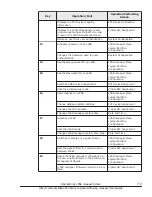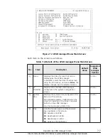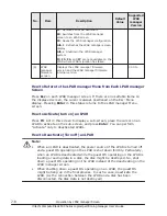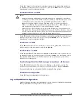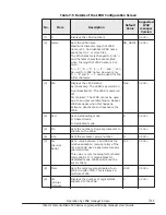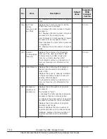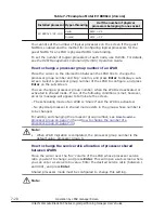
No.
Item
Description
Default
Value
Supported
LPAR
manager
Version
Interface
Card)
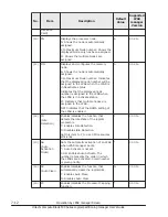
(10) PN
Displays the processor node.
A: Shows the node is automatically
assigned.
0 to Maximum Node number: Shows the
displayed Node only has been assigned.
M: Shows the multiple Nodes are
assigned.
A
01-2X~
(11) MN
Displays and configures the memory
node.
A: Shows the node is automatically
assigned.
0 to Maximum Node number: Indicates
that the displayed node number will be
assigned to the LPAR when the LPAR is
in Deactivate status.
Indicates that the displayed node
number is assigned to the LPAR when
the LPAR is in Activate status.
M: Indicates that multiple nodes are
assigned to the LPAR.
NM: Indicates that the NUMA setting of
the LPAR is enabled.
A
01-2X~
(12) ID
(Idle
Detection)
Enables/disables the function that
detects the idle state of the logical
processors.
Y: Enables Idle Detection.
N: Disables Idle Detection.
Set this item to Y to use CPU resources
efficiently.
Y
01-0X~
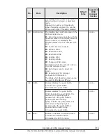
(13) AA
(Auto
Activation
Order)
Sets the automatic activation of an LPAR
when LPAR manager boots.
*: Auto Activate is not set.
1-99: Enables Auto Activate. The
number represents the order in which
the LPARs are activated. Small number
is given priority.
*
01-0X~
(14) AC
(Auto Clear)
Enables/disables the function that
automatically clears the logical SEL.
Y: Enables Auto Clear.
N: Disables Auto Clear.
N
01-0X~
(15) PC
Enables/disables the Processor Capping
function.
*
01-0X~
7-12
Operation by LPAR manager Screen
Hitachi Compute Blade 500 Series Logical partitioning manager User's Guide


