6-20
ELECTRICAL
CORRECT
INCORRECT
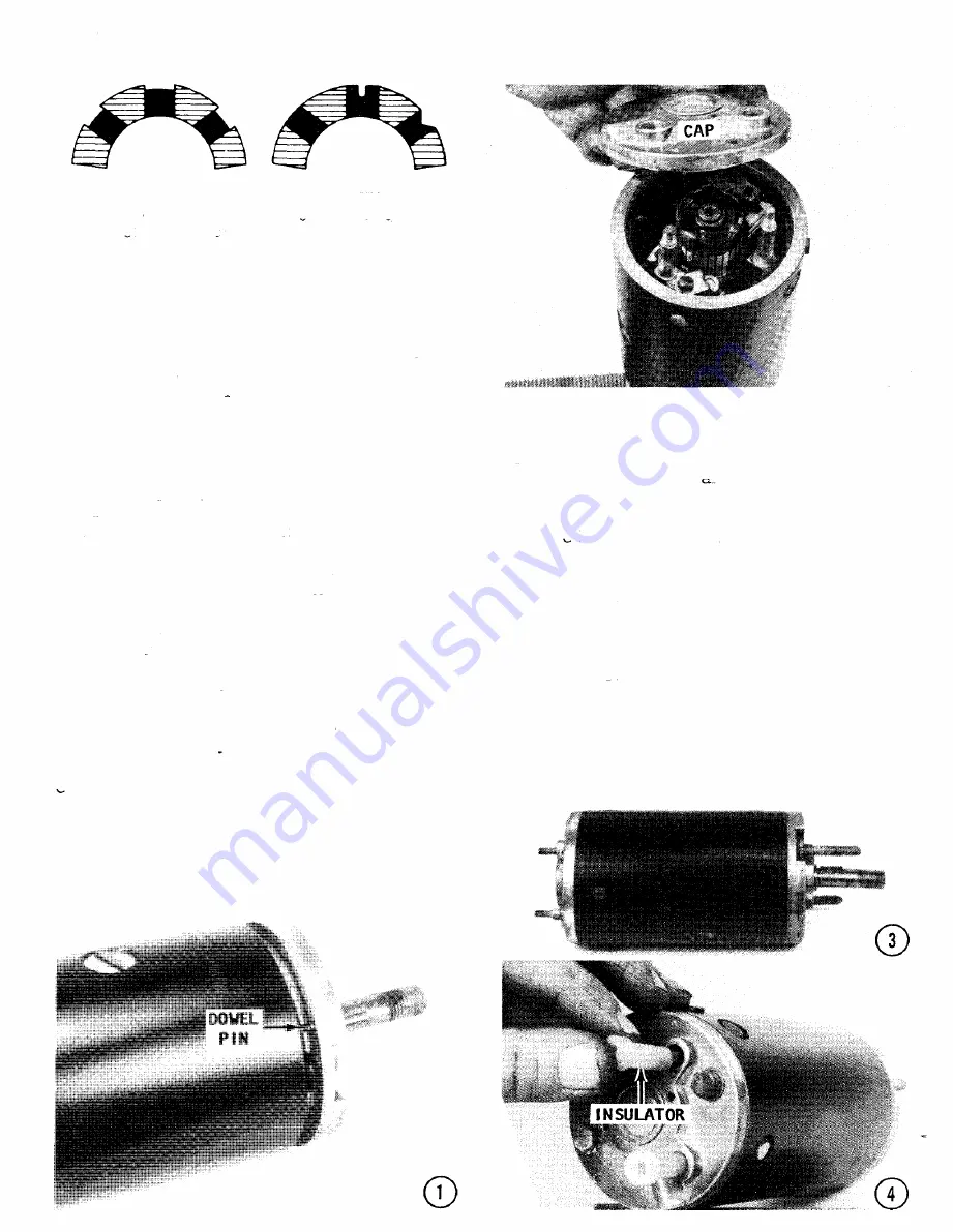
Armature
segments
properly
cleaned
(left)
and im-
properly
cleaned (right).
the turn the upper cap on the shaft
with the
other
hand.
The cap and shaft
should turn
freely
with no sign of binding.
If either
of
these
tests
are
not successful,
the
bear ing
MUST
be replaced.
• Check the amount
of brush wear.
If the
brush is worn more than 50% of its original
size, or to within 1/4" of the base, it should
be replaced.
Replacement
of the brushes
is
a
simple
task.
First,
remove
the
brush
retaining
screw,
and then
remove
the
old
brush and install
a new brush.
Secure
the
new brush in _place with the retaining
screw.
If
the
armature
commutator
requires
turning,
it
should
be turned
in a lathe
to
ensure
accuracy.
The local generator
shop
can
perform
this
task,
usually
for
a very
reasonable
fee.
If the
turning
is accom-
plished by other than generator
shop person-
nel, the following words are necessary.
Af-
ter the turning,
an undercut
should be made.
The insulation
between the commutator
bars
should
be 1-3/4 ",
This undercut
must be
the full width of the insulation
and flat
at
the
bottom.
A triangular
groove
is
NOT
satisfactory.
After
the
undercut
work is
completed
the
slot
should
be
thoroughly
cleaned to remove any foreign
material,
dirt
or
copper
dust.
Sand
the
commutator
LIGHTLY
with
"DO" sandpaper
to
remove
any slight
burrs left
from the undercutting.
After all work has been completed,
test
the
unit again, on the growler.
CD
ASSEMBLING
THE
GENERA
TOR
1-
Slide the armature
into the frame and
align the top armature
cap with the dowel in
the
frame.
Proper
alignment
is achieved
when the dowel in the frame
indexes
into a
matching
hole in the cap.
As the armature
is moved into place, pull back on the brush-
es, and work them
around the commutator
bar.
2- Install
the
end
cap
down
over
the
studs of the field and armature.
Check
to
be sure the dowel in the frame
has indexed
with the hole in the cap.
3-
Install
the two thru-bolts
and secure
the complete
assembly with the nuts.
4-
Place
the two bushings over the ter-
minal studs of the armature
and field.
Se-
cure the bushings in place with the washers
and proper nuts (one terminal
is larger
than
the other).
Summary of Contents for 4906B 4HP 1969
Page 5: ......
Page 87: ...3 46 POWERHEAD Exploded drawing of a 7 5 hp powerhead 1956 58 with principle parts identified...
Page 88: ...CYLINDER BLOCK 3 47 HEAD GASKET RING...
Page 90: ...CYLINDER BLOCK 3 49 THERMOSTAT EXHAUST COVER The...
Page 137: ...4 46 FUEL LEVER AND LOW SPEED...
Page 153: ...4 62 FUEL Exploded view of a pressure tyoe fuel tank with major parts identified...
Page 157: ...4 66 fUEL...
Page 412: ...A 16 APPENDIX Wire Identification 33 hp with Generator 1965 67...
Page 413: ...APPENDIX A 17 o C...
Page 414: ...Wire Identification 33 hp with Generator 1969 70...
Page 415: ...APPENDIX A 19 Wire Identification 35 hp 1957 59...
Page 416: ...A 20 APPENDIX Wire Identification 40 hp Standard Shift with Generator 1960 66...
Page 417: ...APPENDIX A 21 UJ cc b Wire Identification 40 hp Standard Shift with Generator 1967 68...
Page 419: ...APPENDIX Wire Identification 40 hp Electric Shift with Generator 1961 66 A 23...
Page 420: ...A 24 APPENDIX C 00 Wire Identification 40 hp Electric Shift with Generator 1967 68...
Page 421: ...Wire Identification 40 hp Electric Shift with Generator 1969 70...
Page 422: ...NOTES NUMBERS...


