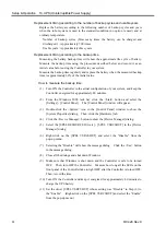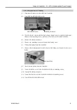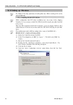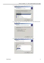
Setup & Operation 8.2 Timing Specifications (I/O Remote Settings)
72
RC420 Rev.9
8.2 Timing Specifications
8.2.1 Design Notes for Remote Input Signals
The following charts indicate timing sequences for the primary operations of the
Controller.
The indicated time lapses (time durations) should be referred to only as reference value
since the actual timing values vary depending on the number of Manipulators and the
number of tasks running, as well as CPU speed of the Controller. Check carefully and
refer to the following charts for the timing interrelation when you enter an input signal.
During system design, make sure that you actuate only one remote input operation at a
time, otherwise an error will occur.
The pulse width of an input signal must be 25 or more milliseconds to be detected.
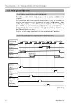
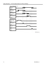
8.2.2 Timing Diagram for Operation Execution Sequence
Power High
Output
Depending on
HOME motion
CmdRunning
Output
MotorOn
Output
AtHome
Output
20
20
20
20
20
20
12
20
150
300
40
50
About 1000
About 1000
MotorOn
Input
MotorOff
Input
Home
Input
PowerHigh
Input
PowerLow
Input
[Unit: msec]
Summary of Contents for RC420
Page 1: ...Rev 9 EM073C1492F ROBOT CONTROLLER RC420 ...
Page 2: ...ROBOT CONTROLLER RC420 Rev 9 ...
Page 12: ...Setup Operation ...
Page 20: ...Setup Operation 1 Safety 10 RC420 Rev 9 ...
Page 30: ...Setup Operation 2 3 Controller Part Names and Functions 20 RC420 Rev 9 ...
Page 50: ...Setup Operation 5 5 Circuit Diagrams EMERGENCY Connector 40 RC420 Rev 9 ...
Page 58: ...Setup Operation 6 3 Pin Assignments STANDARD I O Connector 48 RC420 Rev 9 ...
Page 114: ...Setup Operation 10 UPS Uninterruptible Power Supply 104 RC420 Rev 9 ...
Page 115: ...97 Maintenance This manual contains maintenance procedures for the RC420 Robot Controller ...
Page 116: ...Maintenance RC420 Rev 9 106 ...
Page 138: ...Maintenance 6 Motor Driver Module 128 RC420 Rev 9 ...
Page 170: ...Maintenance 12 Recovering the HDD 160 RC420 Rev 9 ...


