Setup & Operation 5.5 Circuit Diagrams (EMERGENCY Connector)
RC420 Rev.9
39
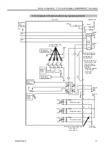
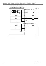
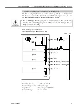
5.5.2 Example 2: External safety relay typical application
Controller
*1 For the protection of
the emergency stop
circuit, the fuse’s
capacity should be
as follows:
- Meets the capacity
of the external
safety relay.
- 1A or less.
External safety relay
(The above diagram
is simplified for
representation.)
Dynamic brake relay
of motor driver
+24V
+24V
Safety Door input 1
External
+24V
Latch release input
9
Safety Door latch release input
Close: latch off
Open: latch on
Emergency
stop detection
Dynamic
brake
control
Emergency
Stop
switches of
an operation
unit
19
1
2
11
12
3
13
5
6
4
14
10
20
8
7
18
17
16
15
External
+24V GND
External
+24V
External
+24V
GND
Ex24V
Fuse *1
External
+24V
GND
Safety Door input 2
Emergency
stop detection
Emergency
stop
detection
Dynamic
brake
control
Summary of Contents for RC420
Page 1: ...Rev 9 EM073C1492F ROBOT CONTROLLER RC420 ...
Page 2: ...ROBOT CONTROLLER RC420 Rev 9 ...
Page 12: ...Setup Operation ...
Page 20: ...Setup Operation 1 Safety 10 RC420 Rev 9 ...
Page 30: ...Setup Operation 2 3 Controller Part Names and Functions 20 RC420 Rev 9 ...
Page 50: ...Setup Operation 5 5 Circuit Diagrams EMERGENCY Connector 40 RC420 Rev 9 ...
Page 58: ...Setup Operation 6 3 Pin Assignments STANDARD I O Connector 48 RC420 Rev 9 ...
Page 114: ...Setup Operation 10 UPS Uninterruptible Power Supply 104 RC420 Rev 9 ...
Page 115: ...97 Maintenance This manual contains maintenance procedures for the RC420 Robot Controller ...
Page 116: ...Maintenance RC420 Rev 9 106 ...
Page 138: ...Maintenance 6 Motor Driver Module 128 RC420 Rev 9 ...
Page 170: ...Maintenance 12 Recovering the HDD 160 RC420 Rev 9 ...

