Setup & Operation 1. Safety
4
RC420 Rev.9
1.2 Safety Precautions
Only trained personnel should design and install the robot system.
Trained personnel are defined as those who have taken robot system training and
maintenance training classes held by the manufacturer, dealer, or local representative
company, or those who understand the manuals thoroughly and have the same knowledge
and skill level as those who have completed the training courses.
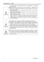
The following items are safety precautions for qualified design or installation
personnel:
Personnel who design and/or construct the robot system with this product must
read the
Safety
chapter in User’s Guide to understand the safety requirements
before designing and/or constructing the robot system. Designing and/or
constructing the robot system without understanding the safety requirements is
extremely hazardous, may result in serious bodily injury and/or severe
equipment damage to the robot system, and may cause serious safety
problems.
The Manipulator and the Controller must be used within the environmental
conditions described in their respective manuals. This product has been
designed and manufactured strictly for use in a normal indoor environment.
Using the product in an environment that exceeds the specified environmental
conditions may not only shorten the life cycle of the product but may also cause
serious safety problems.
The robot system must be used within the installation requirements described in
the manuals. Using the robot system outside of the installation requirements
may not only shorten the life cycle of the product but also cause serious safety
problems.
The interlock of the Safety Door must be functioning when the robot system is
operated. Do not operate the system under the condition that the switch
cannot be turned ON/OFF. (I.E. the condition where the switch is disabled)
(Example: Tape is put around the switch to hold it closed.) Operating the robot
system when the switch is not functioning properly is extremely hazardous and
may cause serious safety problems as the Safety Door input cannot fulfill its
intended function.
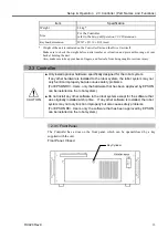
WARNING
Connect input signal wires for Emergency Stop and Safety Door to the
EMERGENCY connector so that the Emergency Stop switch in the operation
unit or the ATTEND (TEACH) control device connected to the OPTIONAL
DEVICE connector always functions. (Refer to the typical application diagram
in the
Setup & Operation 5.5 Circuit Diagrams
.)
Summary of Contents for RC420
Page 1: ...Rev 9 EM073C1492F ROBOT CONTROLLER RC420 ...
Page 2: ...ROBOT CONTROLLER RC420 Rev 9 ...
Page 12: ...Setup Operation ...
Page 20: ...Setup Operation 1 Safety 10 RC420 Rev 9 ...
Page 30: ...Setup Operation 2 3 Controller Part Names and Functions 20 RC420 Rev 9 ...
Page 50: ...Setup Operation 5 5 Circuit Diagrams EMERGENCY Connector 40 RC420 Rev 9 ...
Page 58: ...Setup Operation 6 3 Pin Assignments STANDARD I O Connector 48 RC420 Rev 9 ...
Page 114: ...Setup Operation 10 UPS Uninterruptible Power Supply 104 RC420 Rev 9 ...
Page 115: ...97 Maintenance This manual contains maintenance procedures for the RC420 Robot Controller ...
Page 116: ...Maintenance RC420 Rev 9 106 ...
Page 138: ...Maintenance 6 Motor Driver Module 128 RC420 Rev 9 ...
Page 170: ...Maintenance 12 Recovering the HDD 160 RC420 Rev 9 ...


