Maintenance 13. Maintenance Parts List
13. Maintenance Parts List
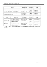
Name
Code
Note
+24V R13A060600300 AES100W-24
Switching Power Supply
+5V
R13A060600600
NSP7-100-X2S2 (for UPS)
50 W
R12R520DRU003
CACR-A5-SU3C
100 W
R12R520DRU004
CACR-01-SU3C
200 W
R12R520DRU005
CACR-02-SU3CY1
400 W
R12R520DRU006
CACR-04-SU3C
Motor Driver
750 W
R12R520DRU007
CACR-08-SU3C
DMB R13A040200100
Regeneration Module
R12R520DRU008
Board No.SKP375
Cooling Fan
R13A060500700
Air Filter
R13A060500800
PNP type
R12R520DIO001
Board No.SKP376
Protected Expansion I/O Board
NPN type R12R520DIO002
Board No.SKP376
Expansion I/O Board
R13R500DIO003
Board No.SKP349
Expansion I/O Cable
R12R500DIO004
Terminal Block
R12R500DIO005
Expansion I/O Connector
R12R500DIO006
R13A090300700
For EPSON RC+ Ver. 3.4 or 3.5
Software Options Key
R13A090301300
For EPSON RC+ Ver. 3.6 or higher
OPTIONAL DEVICE Dummy Plug
R12R500CUP018
EMERGENCY Connector
R13R520DRU014
E. STOP Box
R12B020201
Standard accessory for
UL specifications
Battery R13A060000100
For
UPS
Standard IO Cable for RC420 (3 m)
R12B020205
For USA specification
Terminal Block (USA specification)
R12B061001
For USA specification
Name
Connector for Mouse
and Keyboard
Model Number
Serial Number
Code
Separate Connectors
PC-686BX(PC)-EPC850 From S/N00001 to S/N10000 R13A040000200
CPU
Board
Integrated Connector
SPI-6941-EPC
S/N10001 or later
R13B040002
The CPU board has different model numbers and appearances depending on the dates of the shipping and the
board changeover.
When the CPU board has been replaced for maintenance, the type of CPU board cannot be distinguished only
by serial number. In such a case, see the type of connector for mouse and keyboard or the model number
printed on the CPU board to distinguish the CPU board type.
RC420 Rev.9
161
Summary of Contents for RC420
Page 1: ...Rev 9 EM073C1492F ROBOT CONTROLLER RC420 ...
Page 2: ...ROBOT CONTROLLER RC420 Rev 9 ...
Page 12: ...Setup Operation ...
Page 20: ...Setup Operation 1 Safety 10 RC420 Rev 9 ...
Page 30: ...Setup Operation 2 3 Controller Part Names and Functions 20 RC420 Rev 9 ...
Page 50: ...Setup Operation 5 5 Circuit Diagrams EMERGENCY Connector 40 RC420 Rev 9 ...
Page 58: ...Setup Operation 6 3 Pin Assignments STANDARD I O Connector 48 RC420 Rev 9 ...
Page 114: ...Setup Operation 10 UPS Uninterruptible Power Supply 104 RC420 Rev 9 ...
Page 115: ...97 Maintenance This manual contains maintenance procedures for the RC420 Robot Controller ...
Page 116: ...Maintenance RC420 Rev 9 106 ...
Page 138: ...Maintenance 6 Motor Driver Module 128 RC420 Rev 9 ...
Page 170: ...Maintenance 12 Recovering the HDD 160 RC420 Rev 9 ...


