Setup & Operation 7.2 Protected Expansion I/O Board (Expansion I/O Board - Optional)
RC420 Rev.9
51
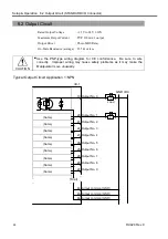
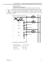
7.2.2 Protected Expansion I/O Board : Input Circuit
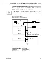
The following diagrams illustrate cases where #48 through #79 (for the first Expansion
I/O Board) are assigned to the Protected Expansion I/O Board’s (or Expansion I/O
Board’s) inputs and outputs. The I/O number assignment depends on the controller
software settings.
Input Voltage Range : + 12 V to 24 V
±
10%
ON Voltage
: + 10.8 V (Min.)
OFF Voltage
: + 5 V (Max.)
Input Current
: 10 mA (TYP) at + 24 V input
CAUTION
■
Use the PNP-type of wiring diagram for CE conformance. Be sure to wire
correctly. Improper wiring may cause safety problems as it may make the
Manipulator move unusually.
Protected Expansion I/O Board
Typical Input Circuit Application 1: NPN
(Same)
(Same)
(Same)
(Same)
(Same)
(Omit)
GND +DC
1 Input No.48 to 51 common
3 Input No.48
4 Input No.49
5 Input No.50
6 Input No.51
51 Input No.52 to 55 common
53 Input No.52
54 Input No.53
~
~
~
2.2 k
Ω
470
Ω
Summary of Contents for RC420
Page 1: ...Rev 9 EM073C1492F ROBOT CONTROLLER RC420 ...
Page 2: ...ROBOT CONTROLLER RC420 Rev 9 ...
Page 12: ...Setup Operation ...
Page 20: ...Setup Operation 1 Safety 10 RC420 Rev 9 ...
Page 30: ...Setup Operation 2 3 Controller Part Names and Functions 20 RC420 Rev 9 ...
Page 50: ...Setup Operation 5 5 Circuit Diagrams EMERGENCY Connector 40 RC420 Rev 9 ...
Page 58: ...Setup Operation 6 3 Pin Assignments STANDARD I O Connector 48 RC420 Rev 9 ...
Page 114: ...Setup Operation 10 UPS Uninterruptible Power Supply 104 RC420 Rev 9 ...
Page 115: ...97 Maintenance This manual contains maintenance procedures for the RC420 Robot Controller ...
Page 116: ...Maintenance RC420 Rev 9 106 ...
Page 138: ...Maintenance 6 Motor Driver Module 128 RC420 Rev 9 ...
Page 170: ...Maintenance 12 Recovering the HDD 160 RC420 Rev 9 ...


