Maintenance 7. DPB (Drive Power Board)
RC420 Rev.9
129
7. DPB (Drive Power Board)
7.1 Layout and Functions
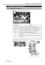
X304
X312
X316
X317
X305
X306
X307
X308
X300
X313
Connector No.
Function
X300
The connector to input the AC200V from the power switch
X301-X304
The connectors to supply motor power to the Motor Driver module.
X305
The connector to supply motor power to the Regeneration module.
X312
The connector to input the +5V and +12V to the backplane.
X313
The connector to connect the DMB interface cable.
X316
The connector to connect the Cooling Fan on the left side as you
face the front.
X317
The connector to connect the Cooling Fan on the right side as you
face the front.
The connectors are on the back side of the DPB as shown below. Remove the Bottom
Cover from the Controller to check these connectors.
X315
X309
X311
X310
X307
X306
X308
Summary of Contents for RC420
Page 1: ...Rev 9 EM073C1492F ROBOT CONTROLLER RC420 ...
Page 2: ...ROBOT CONTROLLER RC420 Rev 9 ...
Page 12: ...Setup Operation ...
Page 20: ...Setup Operation 1 Safety 10 RC420 Rev 9 ...
Page 30: ...Setup Operation 2 3 Controller Part Names and Functions 20 RC420 Rev 9 ...
Page 50: ...Setup Operation 5 5 Circuit Diagrams EMERGENCY Connector 40 RC420 Rev 9 ...
Page 58: ...Setup Operation 6 3 Pin Assignments STANDARD I O Connector 48 RC420 Rev 9 ...
Page 114: ...Setup Operation 10 UPS Uninterruptible Power Supply 104 RC420 Rev 9 ...
Page 115: ...97 Maintenance This manual contains maintenance procedures for the RC420 Robot Controller ...
Page 116: ...Maintenance RC420 Rev 9 106 ...
Page 138: ...Maintenance 6 Motor Driver Module 128 RC420 Rev 9 ...
Page 170: ...Maintenance 12 Recovering the HDD 160 RC420 Rev 9 ...


