Maintenance 5. Switching Power Supply Module
RC420 Rev.9
123
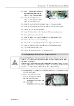
(12) Remove four mounting screws, and
remove the metal plates from the
Switching Power Supply module 1.
(13) Secure the metal plates to a new
Switching Power Supply module 1
with the four mounting screws.
Metal Plate
Metal Plate
(14) Mount the new Switching Power Supply module 1 in the same position.
(15) Secure the new Switching Power Supply module 1 with the screws 1 and 2.
(16) Connect the CN1 and CN2 connectors.
(17) Secure the Bottom Cover to the Controller with the six mounting screws.
(18) Insert the battery into the Controller.
(19) Secure the battery cover to the Controller with the six mounting screws.
(20) Connect the battery connector to the battery.
(21) Connect the connector (X400) of the board for display to the front cover.
(22) Secure the front cover to the Controller with the four mounting screws.
(23) Turn ON the UPS ON/OFF switch.
(24) Connect the all the cables to the back of the Controller.
5.3.2 Replacing Switching Power Supply Module 2:
WARNING
■
Before performing any maintenance procedure, always make sure that the main
power of the Controller is turned OFF and that the high voltage charged area is
completely discharged.
Performing any maintenance procedure while the main power is ON or the high
voltage charged area isn’t discharged completely is extremely hazardous and
may result in electric shock and/or cause serious safety problems.
(1) Perform the step (1) through (9) in the previous section
5.3.1 Replacing Switching
Power Supply Module 1
.
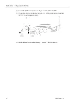
(2) Remove five connectors from the
Switching Power Supply module 2.
CN7 and CN8 connectors:
Projections on the upper side
CN15 connector:
Projections on the lower side
Connectors
Summary of Contents for RC420
Page 1: ...Rev 9 EM073C1492F ROBOT CONTROLLER RC420 ...
Page 2: ...ROBOT CONTROLLER RC420 Rev 9 ...
Page 12: ...Setup Operation ...
Page 20: ...Setup Operation 1 Safety 10 RC420 Rev 9 ...
Page 30: ...Setup Operation 2 3 Controller Part Names and Functions 20 RC420 Rev 9 ...
Page 50: ...Setup Operation 5 5 Circuit Diagrams EMERGENCY Connector 40 RC420 Rev 9 ...
Page 58: ...Setup Operation 6 3 Pin Assignments STANDARD I O Connector 48 RC420 Rev 9 ...
Page 114: ...Setup Operation 10 UPS Uninterruptible Power Supply 104 RC420 Rev 9 ...
Page 115: ...97 Maintenance This manual contains maintenance procedures for the RC420 Robot Controller ...
Page 116: ...Maintenance RC420 Rev 9 106 ...
Page 138: ...Maintenance 6 Motor Driver Module 128 RC420 Rev 9 ...
Page 170: ...Maintenance 12 Recovering the HDD 160 RC420 Rev 9 ...

