Maintenance 12. Recovering the HDD
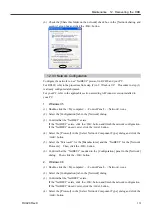
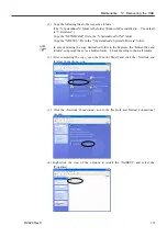
(3) Click the <Next> button in the [Welcome to the Add/Remove Hardware Wizard]
dialog.
(4) Select the <Add/Troubleshoot a device> option button in the [Choose a Hardware
Task] dialog. Click the <Next> button.
(5) Select the “Add a new device” in the [Choose a Hardware Device] dialog. Click
the <Next> button.
(6) Select the <No, I want to select the hardware from a list> option button in the [Find
New Hardware] dialog. Click the <Next> button.
(7) Select the “SPEL RESOURCE Drivers” in the [Hardware Type] dialog. Click the
<Next> button.
(8) Select the applicable Models for each option in the [Select a Device Driver] dialog.
Click the <Next> button.
Expansion I/O Board : SPEL RESOURCE IO *
Pulse Generating Board : SPEL RESOURCE PG *
(The asterisk * indicates each board number.)
(9) Another dialog appears. Click the <OK> button.
(10) Click the <OK> button in the [Add New Hardware Wizard Properties] dialog.
(11) Click the <Yes> button in the [Creating a Forced Configuration] dialog.
(12) Click the <Next> button in the [Start Hardware installation] dialog.
(13) Click the <Finish> button in the [Completing the Add/Remove Hardware Wizard]
dialog.
(14) When you continue reserving address resources of the EPSON RC+ options, click
the <No> button in the [System Setting Change] dialog and repeat the same steps
from (2) for each option.
When you finish reserving address resources of the EPSON RC+ options, click the
<Yes> button in the [System Setting Change] dialog and restart Windows.
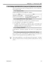
After setting up EPSON RC+, set up UPS and restore the back-up data. For details,
refer to the
Setup & Operation 10.6 Configuring Windows
and
Maintenance 2.5 Backup
of Data
.
)
NOTE
158
RC420 Rev.9
Summary of Contents for RC420
Page 1: ...Rev 9 EM073C1492F ROBOT CONTROLLER RC420 ...
Page 2: ...ROBOT CONTROLLER RC420 Rev 9 ...
Page 12: ...Setup Operation ...
Page 20: ...Setup Operation 1 Safety 10 RC420 Rev 9 ...
Page 30: ...Setup Operation 2 3 Controller Part Names and Functions 20 RC420 Rev 9 ...
Page 50: ...Setup Operation 5 5 Circuit Diagrams EMERGENCY Connector 40 RC420 Rev 9 ...
Page 58: ...Setup Operation 6 3 Pin Assignments STANDARD I O Connector 48 RC420 Rev 9 ...
Page 114: ...Setup Operation 10 UPS Uninterruptible Power Supply 104 RC420 Rev 9 ...
Page 115: ...97 Maintenance This manual contains maintenance procedures for the RC420 Robot Controller ...
Page 116: ...Maintenance RC420 Rev 9 106 ...
Page 138: ...Maintenance 6 Motor Driver Module 128 RC420 Rev 9 ...
Page 170: ...Maintenance 12 Recovering the HDD 160 RC420 Rev 9 ...

