Setup & Operation 7.2 Protected Expansion I/O Board (Expansion I/O Board - Optional)
RC420 Rev.9
53
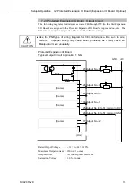
7.2.3 Protected Expansion I/O Board : Output Circuit
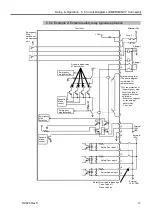
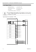
The following diagrams illustrate cases where #48 through #79 (for the first Expansion
I/O Board) are assigned to the Protected Expansion I/O Board’s inputs and outputs. The
I/O number assignment depends on the controller software settings.
CAUTION
■
Use the PNP-type of wiring diagram for CE conformance. Be sure to wire
correctly. Improper wiring may cause safety problems as it may make the
Manipulator move unusually.
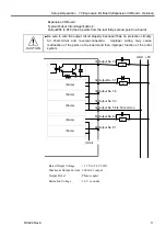
Protected Expansion I/O Board
Typical Output Circuit Application 1: NPN
(Same)
(Same)
(Same)
(Same)
27 Output No. 48
28 Output No. 49
29 Output No. 50
30 Output No. 51
77 Output No. 52
25 Output No.48 to 51 common (+DC)
26 Output No.48 to 51 common (GND)
L
L
GND +DC
(Omit)
~
~
~
~
Rated Output Voltage
: + 12 V to 24 V
±
10%
Maximum Output current : 250 mA/1 output
Output Driver
: N channel power MOS FET
Saturation Voltage
: 1.0 V or under
Summary of Contents for RC420
Page 1: ...Rev 9 EM073C1492F ROBOT CONTROLLER RC420 ...
Page 2: ...ROBOT CONTROLLER RC420 Rev 9 ...
Page 12: ...Setup Operation ...
Page 20: ...Setup Operation 1 Safety 10 RC420 Rev 9 ...
Page 30: ...Setup Operation 2 3 Controller Part Names and Functions 20 RC420 Rev 9 ...
Page 50: ...Setup Operation 5 5 Circuit Diagrams EMERGENCY Connector 40 RC420 Rev 9 ...
Page 58: ...Setup Operation 6 3 Pin Assignments STANDARD I O Connector 48 RC420 Rev 9 ...
Page 114: ...Setup Operation 10 UPS Uninterruptible Power Supply 104 RC420 Rev 9 ...
Page 115: ...97 Maintenance This manual contains maintenance procedures for the RC420 Robot Controller ...
Page 116: ...Maintenance RC420 Rev 9 106 ...
Page 138: ...Maintenance 6 Motor Driver Module 128 RC420 Rev 9 ...
Page 170: ...Maintenance 12 Recovering the HDD 160 RC420 Rev 9 ...

