Setup & Operation 10. UPS (Uninterruptible Power Supply)
10.4.1 While Windows is being booted up
A power failure or voltage drop occurs.
→
The power does not recover.
The power switch is turned OFF accidentally.
→
The switch is left OFF.
Windows is booted up and then it is shut down automatically.
CAUTION
■
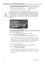
When Windows is hung, even if you turn OFF the Controller, Windows remains
hung until the battery is completely discharged. In this case, turn OFF the
UPS ON/OFF switch. Then, turn ON the UPS ON/OFF switch again after the
UPS is turned OFF. Since the power is not output from the UPS while the UPS
ON/OFF switch is OFF, Windows does not start even though the Controller is
turned ON.
UPS ON/OFF Switch
10.4.2 After Windows is booted up
A power failure or voltage drop occurs.
→
The power recovers during the automatic shutdown.
The power switch is turned OFF accidentally.
→
The power switch is turned ON during the automatic shutdown.
The UPS automatically shuts down Windows when detecting power-off. Once the
shutdown is started, the shutdown cannot be stopped even though the power failure
condition has been corrected. After Windows is shut down, the SHUTDOWN LED
on the front panel of the Controller lights and remains ON. When the Controller is
turned OFF, the UPS power is turned OFF approximately five seconds later.
A power failure or voltage drop occurs.
→
The power does not recover during the automatic shutdown.
The power switch is turned OFF accidentally.
→
The power switch is left OFF.
The UPS automatically shuts down Windows when detecting power-off. After
Windows is shut down, the SHUTDOWN LED on the front panel of the Controller
lights. Approximately five seconds later, the UPS power is turned OFF
automatically.
80
RC420 Rev.9
Summary of Contents for RC420
Page 1: ...Rev 9 EM073C1492F ROBOT CONTROLLER RC420 ...
Page 2: ...ROBOT CONTROLLER RC420 Rev 9 ...
Page 12: ...Setup Operation ...
Page 20: ...Setup Operation 1 Safety 10 RC420 Rev 9 ...
Page 30: ...Setup Operation 2 3 Controller Part Names and Functions 20 RC420 Rev 9 ...
Page 50: ...Setup Operation 5 5 Circuit Diagrams EMERGENCY Connector 40 RC420 Rev 9 ...
Page 58: ...Setup Operation 6 3 Pin Assignments STANDARD I O Connector 48 RC420 Rev 9 ...
Page 114: ...Setup Operation 10 UPS Uninterruptible Power Supply 104 RC420 Rev 9 ...
Page 115: ...97 Maintenance This manual contains maintenance procedures for the RC420 Robot Controller ...
Page 116: ...Maintenance RC420 Rev 9 106 ...
Page 138: ...Maintenance 6 Motor Driver Module 128 RC420 Rev 9 ...
Page 170: ...Maintenance 12 Recovering the HDD 160 RC420 Rev 9 ...


