Setup & Operation 3.3 Cable Connection (Installation)
24
RC420 Rev.9
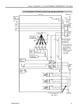
3.3.1 Typical Cable Connection
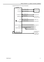
The Manipulator must be connected as follows in order to operate properly. The
diagram indicates a standard cable connection for a single Manipulator configuration.
Connection appearances of the mouse and the keyboard are different depending on the
dates of the shipping and the board changeover.
Separate connectors for mouse and keyboard
Manipulator
M/C POWER
M/C SIGNAL
STANDARD I/O
EMERGENCY
INPUT
Protective Earth
Terminal
Expansion I/O (option)
MONITOR
MOUSE/KEYBOARD
OPTIONAL DEVICE
(1) M/C Power Cable
(2) M/C Signal Cable
(3) STANDARD I/O
(4) EMERGENCY
(5) AC Power Cable
(6) Protective Earth
Input/output unit
E-STOP switch
Safety Door switch
AC200V power
Protective earth
Input/output unit
Monitor
Mouse
Keyboard
ATTEND (TEACH)
Control Device
or Operation Unit
or Dummy Plug
(7)
Controller
(8) Mouse Cable
(9) Keyboard Cable
Summary of Contents for RC420
Page 1: ...Rev 9 EM073C1492F ROBOT CONTROLLER RC420 ...
Page 2: ...ROBOT CONTROLLER RC420 Rev 9 ...
Page 12: ...Setup Operation ...
Page 20: ...Setup Operation 1 Safety 10 RC420 Rev 9 ...
Page 30: ...Setup Operation 2 3 Controller Part Names and Functions 20 RC420 Rev 9 ...
Page 50: ...Setup Operation 5 5 Circuit Diagrams EMERGENCY Connector 40 RC420 Rev 9 ...
Page 58: ...Setup Operation 6 3 Pin Assignments STANDARD I O Connector 48 RC420 Rev 9 ...
Page 114: ...Setup Operation 10 UPS Uninterruptible Power Supply 104 RC420 Rev 9 ...
Page 115: ...97 Maintenance This manual contains maintenance procedures for the RC420 Robot Controller ...
Page 116: ...Maintenance RC420 Rev 9 106 ...
Page 138: ...Maintenance 6 Motor Driver Module 128 RC420 Rev 9 ...
Page 170: ...Maintenance 12 Recovering the HDD 160 RC420 Rev 9 ...


