Maintenance 4. Pin Assignments for the System Connectors
RC420 Rev.9
119
4. Pin Assignments for the System Connectors
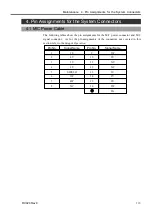
4.1 M/C Power Cable
The following tables show the pin assignments for the M/C power connector and M/C
signal connector. As for the pin assignments of the connectors not covered in this
section, refer to the
Setup & Operation
.
Pin No.
Signal Name
Pin No.
Signal Name
1 1U 9 3W
2 4V 10 2U
3 1V 11 NC
4 4U 12 NC
5 SHIELD 13
3V
6 1W 14 2V
7 4W 15 3U
8 NC 16 2W
FG
Summary of Contents for RC420
Page 1: ...Rev 9 EM073C1492F ROBOT CONTROLLER RC420 ...
Page 2: ...ROBOT CONTROLLER RC420 Rev 9 ...
Page 12: ...Setup Operation ...
Page 20: ...Setup Operation 1 Safety 10 RC420 Rev 9 ...
Page 30: ...Setup Operation 2 3 Controller Part Names and Functions 20 RC420 Rev 9 ...
Page 50: ...Setup Operation 5 5 Circuit Diagrams EMERGENCY Connector 40 RC420 Rev 9 ...
Page 58: ...Setup Operation 6 3 Pin Assignments STANDARD I O Connector 48 RC420 Rev 9 ...
Page 114: ...Setup Operation 10 UPS Uninterruptible Power Supply 104 RC420 Rev 9 ...
Page 115: ...97 Maintenance This manual contains maintenance procedures for the RC420 Robot Controller ...
Page 116: ...Maintenance RC420 Rev 9 106 ...
Page 138: ...Maintenance 6 Motor Driver Module 128 RC420 Rev 9 ...
Page 170: ...Maintenance 12 Recovering the HDD 160 RC420 Rev 9 ...

