User Manual
Chapter 3
GFK-1742F
Jan 2020
Installing and Wiring the DSM314
49
EN3
When this LED is ON, the Axis 3 Drive Enable relay output is active.
EN4
When this LED is ON, the Axis 4 Drive Enable relay output is active.
3.1.2
The DSM COMM (Serial Communications) Connector
The module’s front panel contains a single RJ
-11 connector for serial communications,
labeled “COMM”. It is used to download firmware updates to the DSM module from a
personal computer running the PC Loader or Win Loader utility software. (See Appendix F
for details.)
This serial COMM port connects to the personal computer’s serial port and uses the SNP
protocol and the RS-232 serial communications standard. The baud rate is configurable
from 300 to 19,200 baud. The COMM port is configured using the configuration software.
A 1-meter cable, IC693CBL316, is available from Emerson to connect the COMM port to a
personal computer. This cable uses a 9-pin female D-shell connector for the computer side
and an RJ-11 connector for the DSM314. If a longer cable is used, the maximum
recommended length is 50 feet.
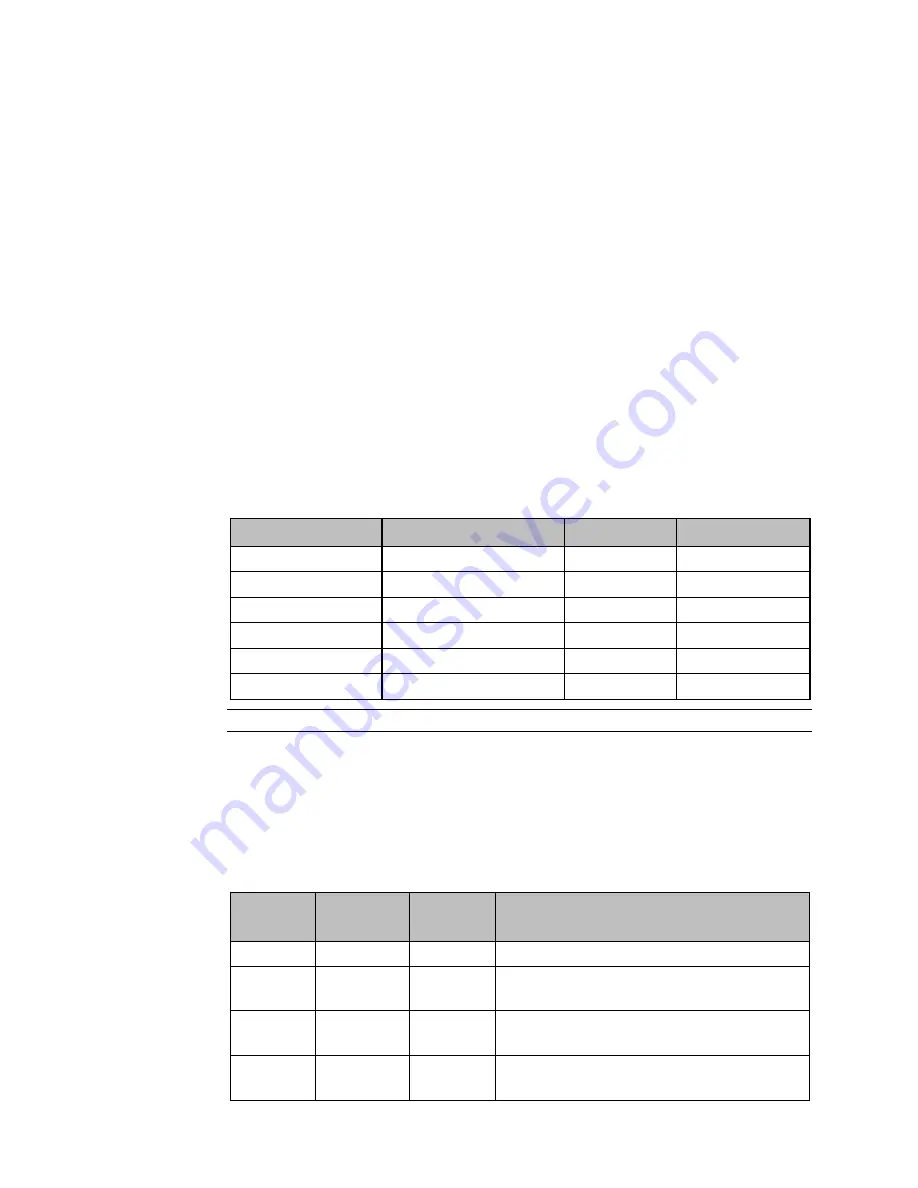
Table 12: DSM314 COMM Port Pin Assignments
RJ-11 Pin Number
9-Pin (female) Number
Signal Name
Description
1
7
CTS
Clear to Send
2
2
TXD
Transmit Data
3
5
0V
Signal Ground
4
5
0V
Signal Ground
5
3
RXD
Receive Data
6
8
RTS
Request to Send
Note:
Pin 1 is at the bottom of the connector when viewed from the front of the module.
3.1.3
I/O Connectors
The DSM314 is a two-axis digital servo/one axis analog velocity interface or four axis analog
servo (Torque Mode and/or Velocity Mode) controller with four 36-pin I/O connectors
labeled A, B, C, and D. The connectors are assigned as follows:
Table 13: Axis I/O Connector Assignments
Connector Axis
Number
Axis Type I/O Usage
A
1
Servo Axis
Closed Loop Digital or Analog Servo Control
B
2
Servo Axis
Aux Axis
Closed Loop Digital or Analog Servo Control or
Position Feedback and auxiliary analog / digital I/O
C
3
Servo Axis
Aux Axis
Closed Loop Analog Servo Control or Position
Feedback and auxiliary analog / digital I/O
D
4
Servo Axis
Aux Axis
Closed Loop Analog Servo Control or Position
Feedback and auxiliary analog / digital I/O


