User Manual
Chapter 5
GFK-1742F
Jan 2020
DSM314 to Host Controller Interface
151
Force Analog Output (Digital Mode) Example
In this example, Axes 1 and 2 are configured as Digital, the beginning DSM314 %Q
address is configured as %Q1, and the beginning %AQ address is configured as
%AQ1. Connectors C and D are set at their default analog output condition (Force
Analog Output).
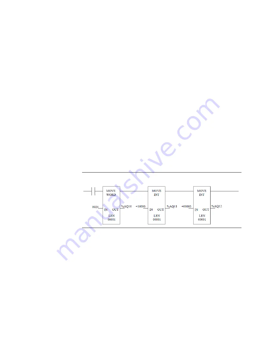
To force an analog output of +5VDC on connector D, the Force Analog Output
immediate command will be issued in the ladder logic program. Since the first %AQ
word was configur
ed as %AQ1, the three words that apply to Connector D (“Axis 4”),
are %AQ10, %AQ11, and %AQ12 (see the paragraph above Table 46 for details).
Since %Q1 was configured as the first %Q bit, the Enable Drive (Servo 4) bit for Axis 4
is %Q67 (see Table 44,
“%Q Discrete Commands”).
So the following values must be moved into the applicable words, using Move
instructions in ladder logic (using a WORD type Move instruction makes it easier to
move a hex number):
%AQ10
Set to 24h (which specifies the Force Analog Output command)
%AQ11
Set to +16000 (which 5VDC)
%AQ12
Set to 0 (this word is not used to convey significant data)
Additionally, the %Q67 bit (Enable Drive) must be set to logic 1.
Figure 62
Analog Velocity Mode
•
In Analog Velocity mode, the Force Analog Output command can be used on
all four connectors to force a voltage output.
•
The Select Analog Output command, discussed in the “Digital Mode” section
above, does not work in Analog mode.
Analog Torque Mode
•
In Analog Torque mode, the Force Analog Output command is NOT available.


