


User Manual
Chapter 8
GFK-1742F
Jan 2020
Follower Motion
227
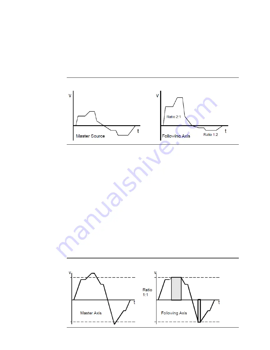
Example 4: Changing the A: B Ratio
One example of variable A:B ratios is to use one ratio while moving positive, and another
when moving negative. Note that determination of positive and negative velocity and
update of the A:B ratio must be done in the host controller or the DSM314 Local Logic
program. In the profile below, the following axis uses a 2:1 ratio when moving positive and
a 1:2 ratio when moving negative.
Figure 98: Changing the A:B Ratio
8.5
Velocity Clamping
Velocity clamping is available using the Velocity Limit set in the Configuration software.
When the master velocity exceeds the configured limit, the following axis will continue to
move at the limit velocity multiplied by the A:B ratio. The Velocity Limit %I bit is set and a
status error is generated to indicate that the slave axis is no longer locked to the master
input positioning. The slave axis has essentially fallen behind the master input.
8.5.1
Example 5: Velocity Clamping
The Velocity Limit is set to 100,000 in this example. Thus, the slave axis velocity is clamped
at 100,000 user units/sec in either direction. When the master axis peaks greater than the
limits, the following axis stays at the limit. After the master slows to under the limit, the
following axis continues tracking the master axis velocity. Counts generated in excess of the
Velocity Limit are lost to the follower. The horizontal dashed lines indicate the velocity
limits. The shaded area indicates the times when the In-Velocity Limit bit is ON and the
following axis is falling behind the master.
Figure 99: Velocity Clamping