


User Manual
Chapter 8
GFK-1742F
Jan 2020
Follower Motion
228
8.6
Unidirectional Operation
Setting the axis Command Direction configuration to Positive Only or Negative Only results
in unidirectional follower motion. Any master axis counts in the zero limited direction are
ignored. No error is generated by counts in the zero limited direction. The In Velocity Limit
%I bit, however, does reflect the presence of a master command in the zero limited
direction.
8.6.1
Example 9: Unidirectional Operation
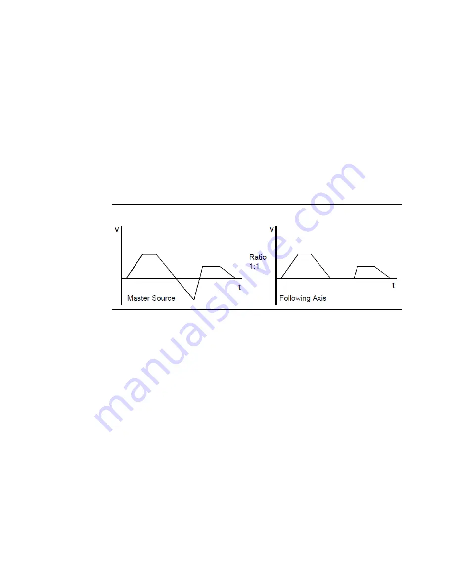
In this example, the Command Direction configuration is set to Positive Only. As shown in
the velocity profile below, the slave axis follows the positive counts, but ignores the negative
counts. Note that when the master is moving negative, the In Velocity Limit %I bit is ON, but
no status error is generated.
Figure 100: Unidirectional Operation
8.7
Enabling the Follower with External Input
Any CTL bit CTL01- CTL32 can be configured as an enable trigger for the follower axis. If a
CTL bit source is configured as an external faceplate input, that input can be used to start
the follower. When no input is selected, the follower is enabled and disabled directly by the
Enable Follower %Q bit. When an input is selected for the Enable Trigger and the Enable
Follower %Q bit is set, the next positive transition of the defined input will instantly enable
the follower. The follower will remain enabled until the Enable Follower %Q bit is cleared.
The faceplate 24v inputs have 5 ms filters that result in a Follower Enable Trigger response
time of 5-7 milliseconds. The faceplate 5v inputs do not have these filters and will provide
an Enable Trigger response time of 2 millisecond or less.
When the Enable Follower trigger occurs, the Commanded Position at that point is captured
in a parameter register so that it can be used in a Programmed Move command. The
position is captured in parameter 226 (for Servo Axis 1), parameter 234 (for Servo Axis 2),
parameter 242 (for Servo Axis 3) or parameter 250 (for Servo Axis 4).
Follower Enabled status is returned in a %I bit for each axis.