


User Manual
Chapter 5
GFK-1742F
Jan 2020
DSM314 to Host Controller Interface
159
4.23 Velocity Loop Proportional Gain. Analog Torque Mode only. The Velocity Loop
Proportional Gain AQ command allows the user to set the velocity regulator
proportional gain in Analog Torque mode. The proportional gain is multiplied by
velocity error (velocity command - velocity feedback) to generate the portion of the
torque command due to the proportional term. Correctly setting this value will
determine how well the velocity regulator performs in the control system. Appendix
D describes a method to correctly tune this parameter. The allowable range for the
velocity loop proportional gain term is 0-32767. The default value is 1500.
4.24 Velocity Loop Integral Gain. Analog Torque Mode only The velocity loop integral
gain AQ command allows the user to set the velocity regulator integral gain in
Analog Torque mode. The integral gain is the term multiplied by the area of the
velocity error (velocity command - velocity feedback) to generate the portion of the
torque command due to the integral term. Correctly setting this value will
determine how well the velocity regulator performs in the control system. Appendix
D describes a method to correctly tune this parameter. The allowable range for the
velocity loop proportional gain term is 0-32767. The default value is 0
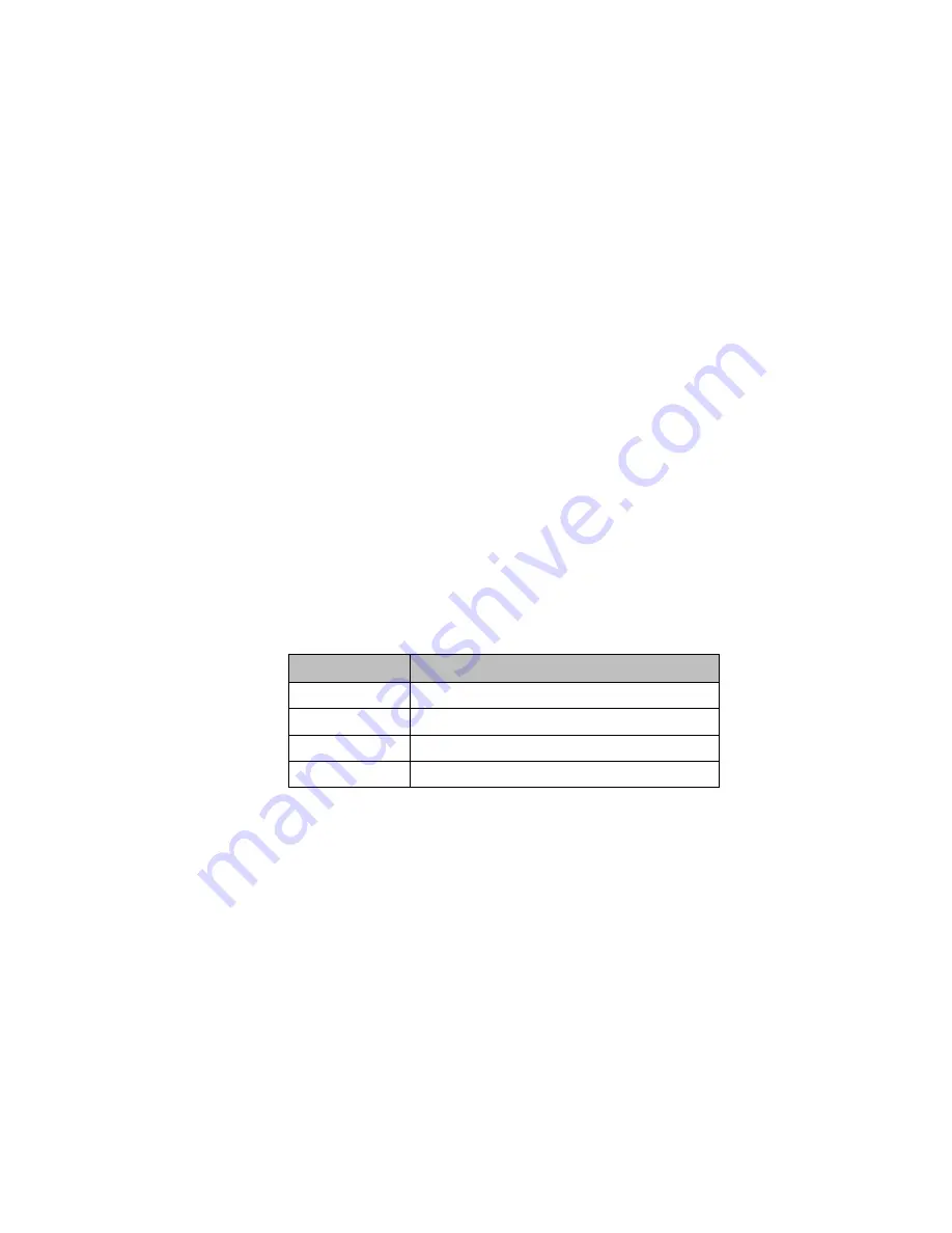
4.25 Torque Command Filter. Analog Torque Mode only. The torque command filter AQ
command allows the user to activate a low pass filter for the velocity regulator
output (Torque Command). The filter is typically used to keep the controller from
exciting a machine resonance. The allowable setting for the Torque Command filter
are shown in Table 48.
Table 47: Torque Filter Commands
TqFilt Mode
Torque Command Low Pass Filter Setting
0
OFF1
1
Low Bandwidth Filter (150 hz 3db point)
2
Medium Bandwidth Filter (250 hz 3db point)
3
High Bandwidth Filter (350 hz. 3db point)
1
Default setting
4.26 Select Analog Output Mode. Digital Mode only. For digital servos, this command lets
you choose what analog signals will be sent to the Analog Output pins (pins 6 and
24) on the four DSM faceplate connectors. The Select Analog Output Mode
command uses a Signal Code to specify the signal to be sent, and a Connector Code
to specify the DSM connector to receive the signal. This command is particularly
useful for servo tuning. This command can be sent from the Command registers for
any axis (1-4).