User Manual
Appendix D
GFK-1742F
Jan 2020
Tuning Digital and Analog Servo Systems
443
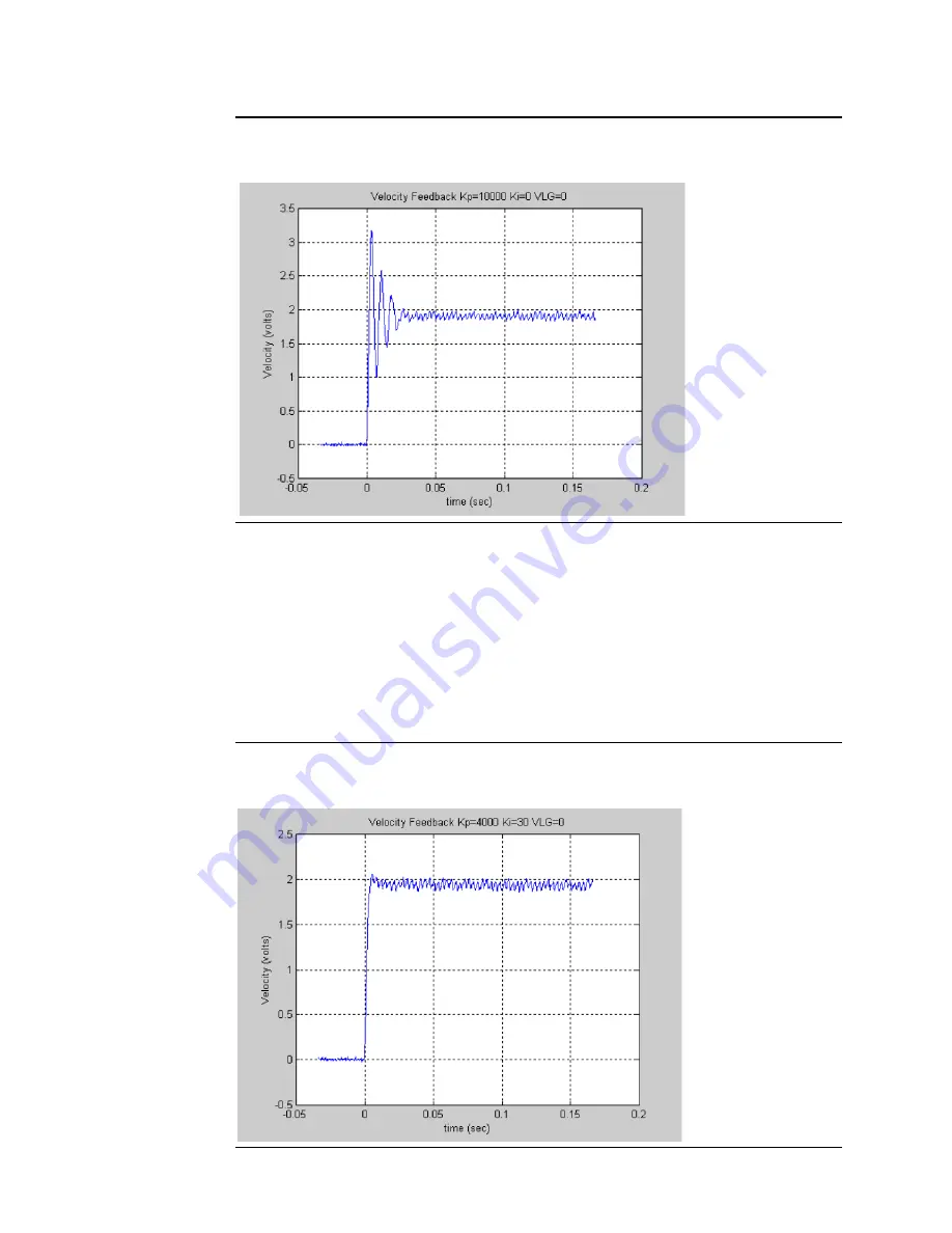
Figure 209: Velocity Loop Step Response Velocity Feedback vs. Time Kp=10000 Ki=0
VLGN = 0
The plot shown above represents an unacceptable response. The loop is exhibiting signs of
instability. Not the Overshoot and ringing following the first peak. The Velocity Loop
Proportional Gain should be significantly decreased to achieve a more stable response.
For this exercise, the response shown corresponding to the Velocity Loop Proportional Gain
(Kp) =4000 will be chosen as the desired response for the system. This value will be used
when tuning the Velocity Loop Integral Gain.
The Velocity Loop Integral Gain is initially zero. You can make a small change to the value
and observe the response.
Figure 210: Velocity Loop Step Response Velocity Feedback vs. Time Kp=4000 Ki=30
VLGN = 0


