


User Manual
Appendix A
GFK-1742F
Jan 2020
Error Reporting
384
A-1.5
System Error Codes
If the DSM encounters errors with the configuration, a motion program, or local logic
block, it will place a System Error code in the Module Status Code register (the first AI
word). When a System Error occurs, the DSM will not update any %I bits or %AI data and
will not respond to any %Q bit or %AQ commands.
So the %Q Clear Error bit has no effect on a System Error. A System Error can only be
cleared by sending a new configuration to the DSM
The following system error codes indicate that the user has entered an invalid DSM
configuration in the configuration/programming software. If one of these errors occurs,
you must change the configuration and store the new configuration to the PLC. Any other
errors of the format Dxxx, Exxx or Fxxx not documented in the table below are unexpected
and should be reported to Emerson.
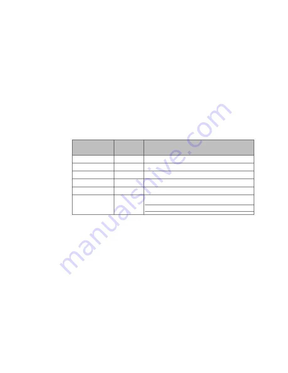
Table 80: System Error Codes
Error Code (hex)
(x = axis number)
System Error
Type
Description
D008
Module
Axis 4 not disabled when Axis 1,2 = Digital Servo
Dx65
Axis
Feedback Source is invalid or not supported
Dx68
Axis
Follower Disable action is not supported
Dx69
Axis
Follower Ramp Makeup Mode is not supported
Dx71
Axis
Invalid digital servo motor type
Dx81
Axis
Analog Servo Cmd mode (Torque mode) not supported.
Note:
DSM314 version 3.0 or later supports Torque Mode.
A-2
DSM Digital Servo Alarms (B0
–
BE)
and
digital servo systems have built in detection and safety shut down circuitry for
many potentially dangerous conditions. The table below reflects that three different
models of servo amplifiers may be used with the DSM, the
Series, the
Series SVU and
the
Series SVM. The following table indicates alarms supported by a particular servo
amplifier and the corresponding DSM error code. Table entries that are blank in the
amplifier columns indicate amplifier alarms not supported by the particular amplifier
serie
s. To clear a servo alarm, amplifier power cycle reset is required. Additionally, a “Clear
Error“
%Q discrete command is required to clear the DSM Error Code. Amplifier alarms not
cleared by power cycle of the amplifier will continue to be reported to the DSM module. A
brief diagnostics section for servo alarms appears at the end of the error alarm tables.