3
Getting Started
This chapter describes how you start configuring your system.
When you power up the chassis, the system performs a power-on self test (POST) during which the line
card status light emitting diodes (LEDs) blink green. The system then loads the Dell Networking Operating
System (OS). Boot messages scroll up the terminal window during this process. No user interaction is
required if the boot process proceeds without interruption.
When the boot process completes, the RPM and line card status LEDs remain online (green) and the
console monitor displays the EXEC mode prompt.
For details about using the command line interface (CLI), refer to the
section in the
chapter.
Console Access
The device has two management ports available for system access: a serial console port and an out-of-
band (OOB) port.
Serial Console
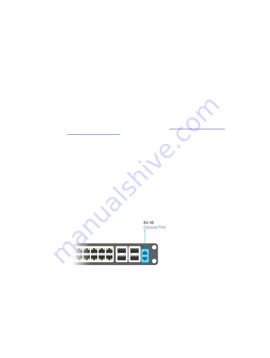
The RJ-45/RS-232 console port is labeled on the chassis. It is in the upper right-hand side, as you face
the I/O side of the chassis.
Figure 1. RJ-45 Console Port
1.
RJ-45 Console Port
50
Getting Started
Summary of Contents for S4820T
Page 1: ...Dell Configuration Guide for the S4820T System 9 8 0 0 ...
Page 282: ...Dell 282 Control Plane Policing CoPP ...
Page 622: ...Figure 81 Configuring Interfaces for MSDP 622 Multicast Source Discovery Protocol MSDP ...
Page 623: ...Figure 82 Configuring OSPF and BGP for MSDP Multicast Source Discovery Protocol MSDP 623 ...
Page 629: ...Figure 86 MSDP Default Peer Scenario 2 Multicast Source Discovery Protocol MSDP 629 ...
Page 630: ...Figure 87 MSDP Default Peer Scenario 3 630 Multicast Source Discovery Protocol MSDP ...
Page 751: ...10 11 5 2 00 00 05 00 02 04 Member Ports Te 1 2 1 PIM Source Specific Mode PIM SSM 751 ...
Page 905: ...Figure 112 Single and Double Tag First byte TPID Match Service Provider Bridging 905 ...
Page 979: ...6 Member not present 7 Member not present Stacking 979 ...
Page 981: ...storm control Storm Control 981 ...
Page 1103: ...Figure 134 Setup OSPF and Static Routes Virtual Routing and Forwarding VRF 1103 ...


