109
i.
=>>?
# % &&#&_^ %`
j.
Use a 10mm wrench to remove the four nuts
%#&##*#%_^ %`"
remove the door/blower/gas valve assembly from the heat exchanger, being careful not to damage the refractory
insulation on the inside of the door (see Refractory Warning on next page) or the electrodes.
k.
Inspect the heat exchanger combustion chamber and vacuum
any debris found on the coil surfaces. If necessary,
the coils may be brushed with a nonabrasive, nonmetallic brush. Do not use cleaning agents, solvents, acid or alkali
products of any type to clean the heat exchanger .
l.
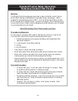
?
. If either shows signs of damage, it must be replaced.
m.
Inspect the burner for heat damage
or other deterioration. Use a non-metallic brush or source of compressed air
to clean off dust or debris from ports.
n.
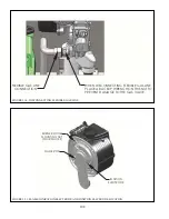
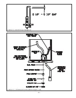
for deposits. Clean any found with steel wool. Do not use sand paper
or Emory cloth for this cleaning. Inspect the ceramic portion of both of these parts for cracks and replace if any are
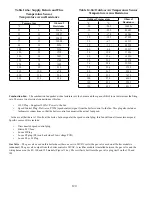
found. Verify that the ignition electrode gap is within the range shown in Figure 13.2
o.
Inspect the blower gas valve assembly
, looking for dust, lint, or other debris that may have been drawn into this
assembly. Excessive deposits may be vacuumed out.
The blower/gas valve assembly used on the 150MBH and 180MBH may be disassembled to expose the
' _ & # ` #'
plate, carefully note the orientation of all parts during disassembly and use care not to damage the swirl plate vanes.
The venturi assembly used on the 80, 100, and 120 cannot be removed from the blower.
Inspect all rubber and plastic components on the blower/gas valve assembly, looking for deterioration. Replace
blower and/or gas valve if deterioration is found.
p.
Inspect and clean the condensate trap
. Place a bucket under the condensate cleanout cap on the bottom of the
boiler (Figure 2.1) to catch water in the trap as well as the ball and ball support. Unscrew the cap, being careful
not to lose the ball or ball support. Flush any debris found in the trap with water – do not use other cleaning agents.
Reassemble the trap as shown in Figure 13.3.
q.
@ Z?Z
, following the above steps in reverse order.
r.
Inspect the vent system to verify that
:
Q
%&[ '# #*#%& %#
Q
&) #&
Q
%&& }&%#\#& \& \&
#&% &\# &&##&% & &
Q
%&& \%\& & )&\
windows,
decks,
etc.
Q
$# % \ ( &)\#%&&& #) #
vent or inlet terminals. Also verify that there are no chemical products containing chlorine, chloride based salts,
#\ )\ %)\&%&#
"&
"B+>-B*?(**(BBB-
((C(F(B,()*
.+I$JB-
$!
")B+B??((
*F(B@(*(?-
"'!$
A )((-(*F )((-
()@+)(*B-'46))*+??
(F)(-
Summary of Contents for PHNTM080
Page 2: ......
Page 9: ...7 Figure 4 1 Minimum Clearances To Combustible Construction...
Page 11: ...9 Figure 5 1 Wall Layout Mounting Hole Location...
Page 12: ...10 Figure 5 2 Boiler Mounting Bracket Installation Boiler Wall Mounting...
Page 39: ...37 FIGURE 7 24 SPLIT VENT SYSTEM FLEX IN ABANDONED MASONRY CHIMNEY VENT OPTIONS 33 38...
Page 63: ...61 This page is intentionally left blank...
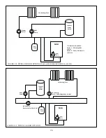
Page 68: ...66 FIGURE 9 2 PIPING METHOD 1 NEAR BOILER PIPING HEATING ONLY...
Page 72: ...70 FIGURE 9 6 PIPING METHOD 1 NEAR BOILER PIPING SHADED BOILER LOOP...
Page 82: ...80 FIGURE 10 4 PROPER INSTALLATION OF HEADER SENSOR...
Page 84: ...82 FIGURE 10 6 INTERNAL WIRING CONNECTIONS DIAGRAM...
Page 85: ...83...
Page 92: ...90 Lighting and Operating Instructions...
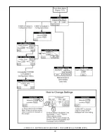
Page 101: ...99 FIGURE 12 5 SETTINGS MENU SEE PART C FOR ADDITIONAL INFORMATION...
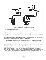
Page 113: ...111 FIGURE 13 2 IGNITION ELECTRODE GAP FIGURE 13 3 CONDENSATE TRAP EXPLODED PARTS VIEW...
Page 125: ...123...
Page 127: ...125 40 33 31 27 28 34 35 37 38 32 39 36 29 30 48 Blower Gas Valve Assembly for 80 100 120...
Page 129: ...127...
Page 131: ...129...
Page 132: ...130...
Page 133: ...131...
Page 135: ...133...
Page 137: ...135 140 141 142 143 144 145...

