74
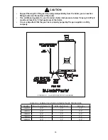
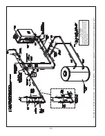
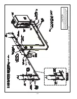
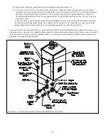
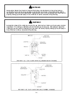
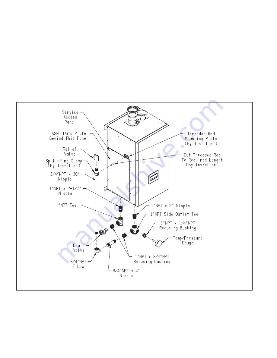
10) Drain Valve (required) – Install the drain valve supplied as shown in Figure 9.9.
11) Low Water Cut-off (may be required by local jurisdiction) – Protection of this boiler against low water and/or
&(' ) &&#} &'' # # $# ' &
# '' # ## )') &# !_`#+
&"&% {# &'' # ''
water
tube
boilers.
In the event that a local jurisdiction insists upon the installation of a low water cut-off with this boiler, a low water
cut-off kit is available that plugs into the low voltage circuit board (see Part X). Install the low water cut-off in the
supply piping at the point prescribed the local jurisdiction (generally at a point above the boiler).
If a probe type low water cut-off is used, be certain that it is located at a point in the piping from which air can escape to an
automatic air vent. Generally, this means that there should be no down-turns in the piping between the low water cut-off and
the point where the automatic air vent is installed. Failure to do this may result in nuisance boiler shut-downs due to small
amounts of air trapped around the probe.
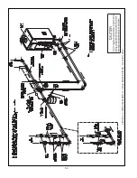
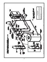
FIGURE 9.9: FACTORY SUPPLIED PIPING AND TRIM INSTALLATION
Summary of Contents for PHNTM080
Page 2: ......
Page 9: ...7 Figure 4 1 Minimum Clearances To Combustible Construction...
Page 11: ...9 Figure 5 1 Wall Layout Mounting Hole Location...
Page 12: ...10 Figure 5 2 Boiler Mounting Bracket Installation Boiler Wall Mounting...
Page 39: ...37 FIGURE 7 24 SPLIT VENT SYSTEM FLEX IN ABANDONED MASONRY CHIMNEY VENT OPTIONS 33 38...
Page 63: ...61 This page is intentionally left blank...
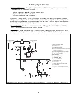
Page 68: ...66 FIGURE 9 2 PIPING METHOD 1 NEAR BOILER PIPING HEATING ONLY...
Page 72: ...70 FIGURE 9 6 PIPING METHOD 1 NEAR BOILER PIPING SHADED BOILER LOOP...
Page 82: ...80 FIGURE 10 4 PROPER INSTALLATION OF HEADER SENSOR...
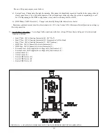
Page 84: ...82 FIGURE 10 6 INTERNAL WIRING CONNECTIONS DIAGRAM...
Page 85: ...83...
Page 92: ...90 Lighting and Operating Instructions...
Page 101: ...99 FIGURE 12 5 SETTINGS MENU SEE PART C FOR ADDITIONAL INFORMATION...
Page 113: ...111 FIGURE 13 2 IGNITION ELECTRODE GAP FIGURE 13 3 CONDENSATE TRAP EXPLODED PARTS VIEW...
Page 125: ...123...
Page 127: ...125 40 33 31 27 28 34 35 37 38 32 39 36 29 30 48 Blower Gas Valve Assembly for 80 100 120...
Page 129: ...127...
Page 131: ...129...
Page 132: ...130...
Page 133: ...131...
Page 135: ...133...
Page 137: ...135 140 141 142 143 144 145...

