16
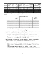
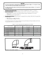
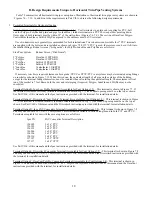
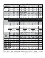
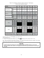
7. Supporting Pipe - Vertical and horizontal sections of pipe must be properly supported. Maximum support spacing is as
follows:
Q
"""# {&) )
Q
# {#&# %# &) )
Q
"## {) #' #&& '&) )
Q
+ # {)# {))
#+&)
Les instructions d´installation du système d´évacuation doivent préciser que les sections horizontales doivent être
) # }#& )&& ) }
instructions divent aussi indiquer les renseignements suivants:
Q
les chaudières de catégories II et IV doivent être installées de façon à empêcher l´accumulation de condensat: et
Q
si nécessaire, les chaudières de catégories II et IV doivent être pourvues de dispositifs d´évacuation du condensat.
8. Allowing for Thermal Expansion -
Q
^""" & %#)'#* )"""
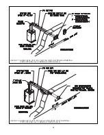
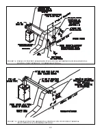
The boiler will always act as an anchor to one end of the vent system. If at all possible, select and install hangers and
wall thimbles so that the vent system can expand towards the terminal. When a straight run of pipe exceeds 20ft and
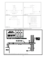
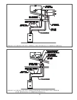
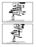
must be restrained at both ends, an offset or expansion loop must be provided (
Figures 7.3a, 7.3b).
When a straight
horizontal run of pipe exceeds 20ft and is restrained at one end with an elbow at the other, avoid putting a hanger or
% &# ##' #&[ % %# _^ %`$#* %
are not permitted.
Q ]#&* \&) &&#[
Part VII-F, G & H of this manual for details.
9. Running PVC Vent Pipe Inside Enclosures and Through Walls - PVC vent pipe must be installed in a manner that permits
adequate air circulation around the outside of the pipe:
Q
Do not enclose PVC venting - Use CPVC in enclosed spaces, even if PVC is installed upstream.
Q
PVC venting may not be used to penetrate combustible or non-combustible walls unless all of the following conditions
are met:
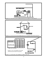
a. The wall penetration is at least 66 inches from the boiler as measured along the vent.
b. The wall is 12” thick or less
c. An airspace of at least that shown in Figure 7.4 is maintained around the OD of the vent.
If any of these conditions cannot be met, use CPVC for the wall penetration.
10. | – The vent system manufacturer may have additional vent system design requirements.
&&'#)| && ##'#]# '#
two sets of instructions, the more restrictive requirements shall govern.
Summary of Contents for PHNTM080
Page 2: ......
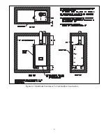
Page 9: ...7 Figure 4 1 Minimum Clearances To Combustible Construction...
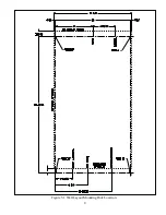
Page 11: ...9 Figure 5 1 Wall Layout Mounting Hole Location...
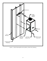
Page 12: ...10 Figure 5 2 Boiler Mounting Bracket Installation Boiler Wall Mounting...
Page 39: ...37 FIGURE 7 24 SPLIT VENT SYSTEM FLEX IN ABANDONED MASONRY CHIMNEY VENT OPTIONS 33 38...
Page 63: ...61 This page is intentionally left blank...
Page 68: ...66 FIGURE 9 2 PIPING METHOD 1 NEAR BOILER PIPING HEATING ONLY...
Page 72: ...70 FIGURE 9 6 PIPING METHOD 1 NEAR BOILER PIPING SHADED BOILER LOOP...
Page 82: ...80 FIGURE 10 4 PROPER INSTALLATION OF HEADER SENSOR...
Page 84: ...82 FIGURE 10 6 INTERNAL WIRING CONNECTIONS DIAGRAM...
Page 85: ...83...
Page 92: ...90 Lighting and Operating Instructions...
Page 101: ...99 FIGURE 12 5 SETTINGS MENU SEE PART C FOR ADDITIONAL INFORMATION...
Page 113: ...111 FIGURE 13 2 IGNITION ELECTRODE GAP FIGURE 13 3 CONDENSATE TRAP EXPLODED PARTS VIEW...
Page 125: ...123...
Page 127: ...125 40 33 31 27 28 34 35 37 38 32 39 36 29 30 48 Blower Gas Valve Assembly for 80 100 120...
Page 129: ...127...
Page 131: ...129...
Page 132: ...130...
Page 133: ...131...
Page 135: ...133...
Page 137: ...135 140 141 142 143 144 145...

