107
1)
Continuously
:
a.
Keep the area around the boiler
free from combustible materials, gasoline and other
)& ( &
b.
Keep the area around the combustion air inlet terminal
free from contaminates.
c.
Keep the boiler room ventilation openings
open and unobstructed.
2)
Monthly Inspections
:
a.
Inspect the vent piping and outside air intake piping
to verify they are open, unobstructed and free
from leakage or deterioration. Call the service technician to make repairs if needed.
b.
Inspect the condensate drain system
to verify it is leak tight, open and unobstructed. Call the service
technician if the condensate drain system requires maintenance.
c.
Inspect the water and gas lines
to verify they are free from leaks. Call the service technician to make
repairs
if
required.
4)
Annual Inspections and Service
: In addition to the inspections listed above, the following should be performed by a
service technician once every year.
a.
Follow the procedure
for turning the boiler off found in the Lighting and Operating Instructions, on page 90.
b.
Turn off all power
to the boiler.
c.
Inspect the wiring
to verify the conductors are in good condition and attached securely.
d.
Verify that the gas shutoff
shown in Figure 8.1 is closed
e.
;<
#%)) _^ %`
f.
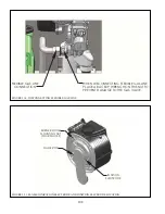
Unplug the electrical connection
to the gas valve.
g.
Disconnect the air proving switch tube
from the gas valve outlet tap.
h.
Unplug the power and speed control cables
from the blower.
$!
A*))(?BB)
AB -
$!
F(A)*))B-
))BF(-
"'!$<"!!!$
F>-#*?B?A-
()BB(B-BBBA-
"())v))@xD(>( Ax*-#
(y*B(A((*)z(-v(D(
vBBxD()(Fv)x-
"&
>-+B>-"?(*F(B?C?)F
*F?(49-6-((,
)AA-FBBF)
(*(A-
Summary of Contents for PHNTM080
Page 2: ......
Page 9: ...7 Figure 4 1 Minimum Clearances To Combustible Construction...
Page 11: ...9 Figure 5 1 Wall Layout Mounting Hole Location...
Page 12: ...10 Figure 5 2 Boiler Mounting Bracket Installation Boiler Wall Mounting...
Page 39: ...37 FIGURE 7 24 SPLIT VENT SYSTEM FLEX IN ABANDONED MASONRY CHIMNEY VENT OPTIONS 33 38...
Page 63: ...61 This page is intentionally left blank...
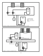
Page 68: ...66 FIGURE 9 2 PIPING METHOD 1 NEAR BOILER PIPING HEATING ONLY...
Page 72: ...70 FIGURE 9 6 PIPING METHOD 1 NEAR BOILER PIPING SHADED BOILER LOOP...
Page 82: ...80 FIGURE 10 4 PROPER INSTALLATION OF HEADER SENSOR...
Page 84: ...82 FIGURE 10 6 INTERNAL WIRING CONNECTIONS DIAGRAM...
Page 85: ...83...
Page 92: ...90 Lighting and Operating Instructions...
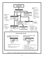
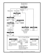
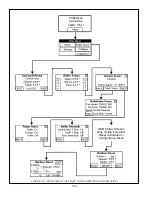
Page 101: ...99 FIGURE 12 5 SETTINGS MENU SEE PART C FOR ADDITIONAL INFORMATION...
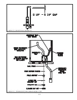
Page 113: ...111 FIGURE 13 2 IGNITION ELECTRODE GAP FIGURE 13 3 CONDENSATE TRAP EXPLODED PARTS VIEW...
Page 125: ...123...
Page 127: ...125 40 33 31 27 28 34 35 37 38 32 39 36 29 30 48 Blower Gas Valve Assembly for 80 100 120...
Page 129: ...127...
Page 131: ...129...
Page 132: ...130...
Page 133: ...131...
Page 135: ...133...
Page 137: ...135 140 141 142 143 144 145...


