14
All of these systems are considered “direct vent” because the air for combustion is drawn directly from the outdoors into the
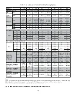
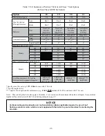
boiler. One of the vent option columns in the tables referenced above must match the planned vent and air intake system exactly.
Design details applying to all vent systems are shown in this section. Observe all design requirements in this section, as well as
those unique to the type of system being installed:
Q %( (! {$'
Q " %( ( $'
Q %( (
1. Approved Vent Systems and Materials – The following materials and vent systems may be used to vent this boiler:
Q """" &$^"&\# &}"
Q ""& & # " &$+
"" \&""'\ &'# |) &#"
of foam core PVC is not permitted for venting. PVC vent pipe may not be used to vent this boiler in Canada.
Q }" & %)
Q }" & %)
Q "#^]}" & %)
Use PVC and/or CPVC for the air intake system. PVC may be used for all air intake piping between the intake terminal and
the boiler.
When CPVC and/or PVC pipe is used, it must be joined using primer and cement that is listed for use with the pipe material
being joined (PVC, CPVC, or CPVC to PVC).
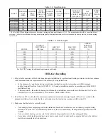
2. Vent Components Supplied with this Boiler – This boiler is supplied with some of the components needed for 3” CPVC/PVC
venting (Vent Option 2). A list of these components is supplied in Table 7.26. Components not supplied may be procured
locally. The CPVC Pipe and elbow supplied with this boiler are not listed to ULC S636 and may not be used in Canada.
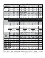
3. Maximum Vent and Air Intake Lengths - The maximum length of the vent air intake piping depends upon the vent option
selected and the boiler size.
See Tables 7.5, 7.13 or 7.21
for the maximum vent lengths. These maximum lengths apply
to both the vent and intake piping (e.g. Option 1 may have up to 60ft of intake and 60ft of vent piping). For all vent
\#%##' $\&+ && #''& &\
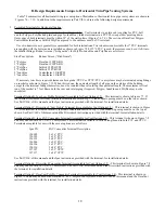
the maximum allowable vent length must be reduced by the amount shown in Table
7.1
for each additional elbow used.
$ %)&
$#' &' ## &&& ' &&#& &"""
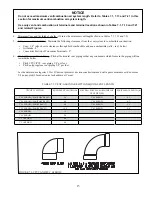
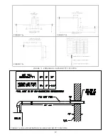
elbows be “1/4 Bend” (Sanitary 90° El) or “Long Sweep 1/4 Bend” type elbows (Figure 7.2). In this manual “sanitary” and
“long sweep” elbows are treated as having the same equivalent length.
Example:
A 3” twin pipe horizontal CPVC/PVC vent system is planned for a horizontally vented 120MBH model which has the
following components in the vent system:
1 ft CPVC Straight Pipe
90 CPVC Elbow (short bend)
1-1/2 ft CPVC Straight Pipe
Coupling
10 ft PVC Straight Pipe
90 PVC Elbow (Sanitary Elbow Design)
15 ft PVC Straight Pipe
PVC Coupling Terminal
The Vent Option #2 column in Table 7.5 describes a horizontal direct vent system using 3” CPVC and PVC pipe. From this
!"$%& &&'
Table 7.1, we see that the equivalent length of the 90 PVC elbow is 4ft and that the equivalent length of the coupling is 0ft.
The total equivalent length of the planned venting system is therefore:
*+!"68%* &!"$%;68*+!"68%* 68%*+!"6
+ 4ft (PVC 90 Sanitary Elbow) + 15ft (Straight PVC) + 0ft (Coupling Terminal) = 31.5ft.
Since Table 7.5 shows a maximum allowable vent length of 135ft, the planned vent system length is acceptable
$#*) %&# $' & &#* ')
length. See Sections VII-C or VII-D for details.
Summary of Contents for PHNTM080
Page 2: ......
Page 9: ...7 Figure 4 1 Minimum Clearances To Combustible Construction...
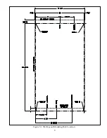
Page 11: ...9 Figure 5 1 Wall Layout Mounting Hole Location...
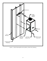
Page 12: ...10 Figure 5 2 Boiler Mounting Bracket Installation Boiler Wall Mounting...
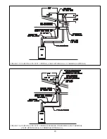
Page 39: ...37 FIGURE 7 24 SPLIT VENT SYSTEM FLEX IN ABANDONED MASONRY CHIMNEY VENT OPTIONS 33 38...
Page 63: ...61 This page is intentionally left blank...
Page 68: ...66 FIGURE 9 2 PIPING METHOD 1 NEAR BOILER PIPING HEATING ONLY...
Page 72: ...70 FIGURE 9 6 PIPING METHOD 1 NEAR BOILER PIPING SHADED BOILER LOOP...
Page 82: ...80 FIGURE 10 4 PROPER INSTALLATION OF HEADER SENSOR...
Page 84: ...82 FIGURE 10 6 INTERNAL WIRING CONNECTIONS DIAGRAM...
Page 85: ...83...
Page 92: ...90 Lighting and Operating Instructions...
Page 101: ...99 FIGURE 12 5 SETTINGS MENU SEE PART C FOR ADDITIONAL INFORMATION...
Page 113: ...111 FIGURE 13 2 IGNITION ELECTRODE GAP FIGURE 13 3 CONDENSATE TRAP EXPLODED PARTS VIEW...
Page 125: ...123...
Page 127: ...125 40 33 31 27 28 34 35 37 38 32 39 36 29 30 48 Blower Gas Valve Assembly for 80 100 120...
Page 129: ...127...
Page 131: ...129...
Page 132: ...130...
Page 133: ...131...
Page 135: ...133...
Page 137: ...135 140 141 142 143 144 145...


