113
XIV. Troubleshooting
The following pages contain trouble shooting tables for use in diagnosing control problems. When using these tables
the following should be kept in mind:
1) This information is only meant to be used by a professional heating technician as an aid in diagnosing boiler
problems.
2) Where applicable, follow all precautions outlined in the Section XI (Start-up and Checkout).
3) All controls on the boiler are tested at least once in the manufacturing process and a defective control or
component is generally the least likely cause. Before replacing a component, try to rule out all other possible causes.
A. Using the Diagnostics Menu
The plain text display provided with this boiler provides an easy means of identifying most common problems. In the event that
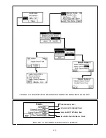
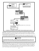
the control system detects a problem, such as an open limit or defective sensor, the Active Fault button shown in Figure 14.0 will
&###!&#$# % # )^' #
# % ^#\## %# )# #
of a defective temperature sensor, a defect indicator will also show up on the status screens where the corresponding temperature
is normally displayed. See Figure 14.0 for an example of this.
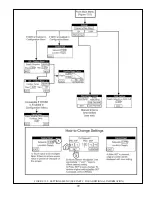
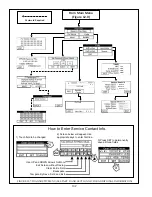
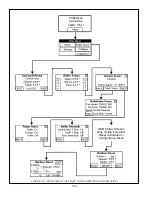
The complete Diagnostics Menu is shown in Figure 12.7. The screens on this menu provide the following information:
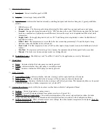
1) For Service Contact
- Displays the service contact information entered in Section XII, Step D.
2) About
- Displays the software versions for both the boiler control (R7910B) and the display
3) Fault
Menu
- Provides status of different types of faults by category. When a particular fault exists, the button for that
%' #_^ %*`#*#' ^ %
\##&}##^& )
lockout. Fault categories include:
"&
0
+B>-F>-(>-!*(C))*@
A@)AB@A?(B(-"(
B?(BB?)B(*)B
)*A-
0
)BA?FBA*-A)@
)A)B?A-
"&
0
!*)(*AB*F+BA-
0
B@)(*B?)-
0
&@(?(?
)(-
0
?(A@*?(
?BB-
0
A,()B(*BB)B*-
0
&@(?(?"##)B
()(-
0
"(B)BBBB*B
**FA-
Summary of Contents for PHNTM080
Page 2: ......
Page 9: ...7 Figure 4 1 Minimum Clearances To Combustible Construction...
Page 11: ...9 Figure 5 1 Wall Layout Mounting Hole Location...
Page 12: ...10 Figure 5 2 Boiler Mounting Bracket Installation Boiler Wall Mounting...
Page 39: ...37 FIGURE 7 24 SPLIT VENT SYSTEM FLEX IN ABANDONED MASONRY CHIMNEY VENT OPTIONS 33 38...
Page 63: ...61 This page is intentionally left blank...
Page 68: ...66 FIGURE 9 2 PIPING METHOD 1 NEAR BOILER PIPING HEATING ONLY...
Page 72: ...70 FIGURE 9 6 PIPING METHOD 1 NEAR BOILER PIPING SHADED BOILER LOOP...
Page 82: ...80 FIGURE 10 4 PROPER INSTALLATION OF HEADER SENSOR...
Page 84: ...82 FIGURE 10 6 INTERNAL WIRING CONNECTIONS DIAGRAM...
Page 85: ...83...
Page 92: ...90 Lighting and Operating Instructions...
Page 101: ...99 FIGURE 12 5 SETTINGS MENU SEE PART C FOR ADDITIONAL INFORMATION...
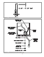
Page 113: ...111 FIGURE 13 2 IGNITION ELECTRODE GAP FIGURE 13 3 CONDENSATE TRAP EXPLODED PARTS VIEW...
Page 125: ...123...
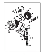
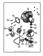
Page 127: ...125 40 33 31 27 28 34 35 37 38 32 39 36 29 30 48 Blower Gas Valve Assembly for 80 100 120...
Page 129: ...127...
Page 131: ...129...
Page 132: ...130...
Page 133: ...131...
Page 135: ...133...
Page 137: ...135 140 141 142 143 144 145...

