97
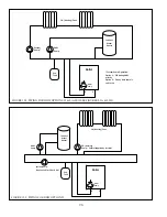
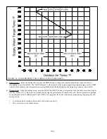
DHW Priority -
Like all boilers, the Phantom is capable of regulating only one target boiler water temperature at any given
time. This means that priority must be given to either the CH or DHW target temperature. For this reason, the Phantom gives
#!]&&# & %'# ##"!&!] * #
still simultaneous calls for DHW and CH at the end of this time, the boiler will attempt to maintain the target CH temperature
and operate the pump/s needed to satisfy the call for heat. The boiler will once again give priority to the DHW temperature
when either of the following events occur:
Q
The call for CH ends.
Q
The call for DHW is removed and then restored.
Regardless of the DHW option selected, the target water temperature will always change from that for DHW to CH if the
simultaneous demand exceeds 60 min.
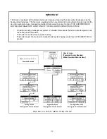
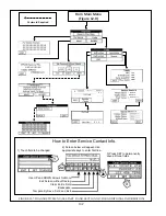
4) %#~"#% ##&)&"% $#
allows the user to access rarely needed% $# &;
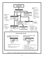
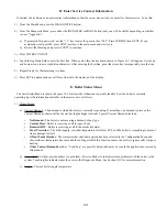
FACTORY SET -
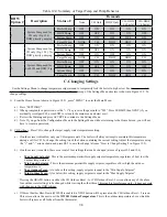
$# '#% & % $#
used to restore all factory settings if a large number of settings are suspect or if the original control is replaced by one that is
programed for use on another size Phantom. Pressing this button brings up the screen shown in Figure 12.1. Press the model
#& && #&]## #%&\# ' #]##
& && #&\$ ]## #% &#\#' # %
$#&)&"% ###% %#
Section (XII).
"&
"B+>-B)()*)-$
*B(?B)-!*B
)))())+)()*?B-*B(>(*(
)BBB)(BB@B,(-
Summary of Contents for PHNTM080
Page 2: ......
Page 9: ...7 Figure 4 1 Minimum Clearances To Combustible Construction...
Page 11: ...9 Figure 5 1 Wall Layout Mounting Hole Location...
Page 12: ...10 Figure 5 2 Boiler Mounting Bracket Installation Boiler Wall Mounting...
Page 39: ...37 FIGURE 7 24 SPLIT VENT SYSTEM FLEX IN ABANDONED MASONRY CHIMNEY VENT OPTIONS 33 38...
Page 63: ...61 This page is intentionally left blank...
Page 68: ...66 FIGURE 9 2 PIPING METHOD 1 NEAR BOILER PIPING HEATING ONLY...
Page 72: ...70 FIGURE 9 6 PIPING METHOD 1 NEAR BOILER PIPING SHADED BOILER LOOP...
Page 82: ...80 FIGURE 10 4 PROPER INSTALLATION OF HEADER SENSOR...
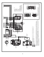
Page 84: ...82 FIGURE 10 6 INTERNAL WIRING CONNECTIONS DIAGRAM...
Page 85: ...83...
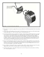
Page 92: ...90 Lighting and Operating Instructions...
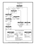
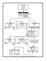
Page 101: ...99 FIGURE 12 5 SETTINGS MENU SEE PART C FOR ADDITIONAL INFORMATION...
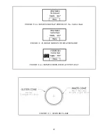
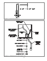
Page 113: ...111 FIGURE 13 2 IGNITION ELECTRODE GAP FIGURE 13 3 CONDENSATE TRAP EXPLODED PARTS VIEW...
Page 125: ...123...
Page 127: ...125 40 33 31 27 28 34 35 37 38 32 39 36 29 30 48 Blower Gas Valve Assembly for 80 100 120...
Page 129: ...127...
Page 131: ...129...
Page 132: ...130...
Page 133: ...131...
Page 135: ...133...
Page 137: ...135 140 141 142 143 144 145...

