138
factory if it is not possible to reduce the CO level below 200PPM air free within the range of CO2s shown for the fuel and
altitude at which the boiler is being used.
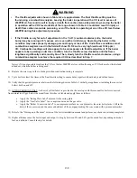
8) Replace the screw cap in the vent adapter when combustion testing is complete.
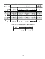
` " ) ## % % ' #&&' #
10) Verify that the gas inlet pressure is between the following shown in Table A.5 with all gas appliances (including the converted
boiler) both on and off.
11) LP CONVERSIONS ONLY - A sheet of yellow labels is provided in the envelope with this manual for boilers converted
from natural to LP gas. Select the model from this sheet of labels and apply them as follows:
a. Apply the “Rating Plate Label” adjacent to the rating plate.
b. Apply the “Gas Valve Label” to a conspicuous area on the gas valve.
c. Apply the “Boiler Conversion Label” to a conspicuous surface on, or adjacent to, the outer boiler jacket. Fill in the
date of the conversion and the name and address of the company making the conversion with a permanent marker.
12) Refer to the “Start-up and Checkout” section of the boiler installation manual and perform any checks not already completed.
13) Higher altitudes cause the boiler input and output to drop by between 0% and 2.4% per thousand feet, depending on model,
fuel, and altitude. Consult factory for details.
"&
0
!,()?!*"-:BB+)-! )(*
(()*(>-#A*B?$A+
:66%%.((,()*)+B-#A*
B?$:A(?!*"-;((,(
)*)+B@A*B$A*?
:66%%.(,()B(-
0
A(,()\I(F?J@*
*()*(6j+A? -$B*
)(BB)@B,(-')
)*(>( ??6j$:AI?A4666BB)J
$-)*(?BB*(BA,()-*
BB*B(@(?F?(C)
)*(-!@?((F?@(
)*(>AD($:*BY-
Summary of Contents for PHNTM080
Page 2: ......
Page 9: ...7 Figure 4 1 Minimum Clearances To Combustible Construction...
Page 11: ...9 Figure 5 1 Wall Layout Mounting Hole Location...
Page 12: ...10 Figure 5 2 Boiler Mounting Bracket Installation Boiler Wall Mounting...
Page 39: ...37 FIGURE 7 24 SPLIT VENT SYSTEM FLEX IN ABANDONED MASONRY CHIMNEY VENT OPTIONS 33 38...
Page 63: ...61 This page is intentionally left blank...
Page 68: ...66 FIGURE 9 2 PIPING METHOD 1 NEAR BOILER PIPING HEATING ONLY...
Page 72: ...70 FIGURE 9 6 PIPING METHOD 1 NEAR BOILER PIPING SHADED BOILER LOOP...
Page 82: ...80 FIGURE 10 4 PROPER INSTALLATION OF HEADER SENSOR...
Page 84: ...82 FIGURE 10 6 INTERNAL WIRING CONNECTIONS DIAGRAM...
Page 85: ...83...
Page 92: ...90 Lighting and Operating Instructions...
Page 101: ...99 FIGURE 12 5 SETTINGS MENU SEE PART C FOR ADDITIONAL INFORMATION...
Page 113: ...111 FIGURE 13 2 IGNITION ELECTRODE GAP FIGURE 13 3 CONDENSATE TRAP EXPLODED PARTS VIEW...
Page 125: ...123...
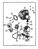
Page 127: ...125 40 33 31 27 28 34 35 37 38 32 39 36 29 30 48 Blower Gas Valve Assembly for 80 100 120...
Page 129: ...127...
Page 131: ...129...
Page 132: ...130...
Page 133: ...131...
Page 135: ...133...
Page 137: ...135 140 141 142 143 144 145...

