8
V Mounting The Boiler
A. Wall Mounting
1) If the boiler is installed on a framed wall, minimum acceptable framing is 2 x 4 studs on 16” centers. The boiler
mounting holes are on 16” centers for installation between two studs at the standard spacing. In cases where the
boiler cannot be centered between the studs, or where the studs are spaced closer than 16” apart, the boiler may be
anchored to ¾” plywood or horizontal 2 x 4s anchored to the studs.
2) 5/16” x 2” lag screws and washers are provided for mounting this boiler. These lag screws are intended for mount-
ing the boiler directly onto studs covered with ½” sheathing. When the boiler is attached to other types of construc-
tion, such as masonry, use fasteners capable of supporting the weight of the boiler and attached piping in accor-
dance with good construction practice and applicable local codes.
3) Make sure that the surface to which the boiler is mounted is plumb.
4) Before mounting the boiler, make sure that wall selected does not have any framing or other construction that will
interfere with the vent pipe penetration.
` #&# \&&&& #)&#'\
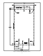
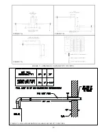
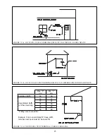
use Figure 5.1 to locate holes “A” and “B”. Make sure that the horizontal centerline of these holes is level. Holes
“C” and “D” may also be drilled at this time or after the boiler is hung on the wall. If the 5/16” x 2” lag screws are
used, drill 3/16” pilot holes.
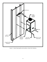
6) The wall mounting hook is used to secure the boiler to the shipping pallet. Remove this hook from the pallet and
secure to the wall using the 5/16” x 2” lag screws and washers, or other suitable anchors as appropriate (Figure
5.2). Make sure the hook is level.
7) Hang the boiler on the wall hook as shown in Figure 5.2.
8) If not already done in Step (5) locate and drill holes “C” and “D” using the obround slots in the bottom mounting
%#%#' %#*+%'\# _^ %-
ure 5.2).
9) Verify that the front of the boiler is plumb. If it is not, install washers at holes “C” and “D” between the bottom
%%&#'&[
CAUTION
This boiler weighs as much as 119 pounds:
0 !? BB D( * ? )( F-
0 .F ( ? )( F (( B*
(BB ? * BB ? ? ?-
W( (*, D(F ) A B D()
(BB *- ! D() F B A
D() ? *?-
Summary of Contents for PHNTM080
Page 2: ......
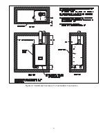
Page 9: ...7 Figure 4 1 Minimum Clearances To Combustible Construction...
Page 11: ...9 Figure 5 1 Wall Layout Mounting Hole Location...
Page 12: ...10 Figure 5 2 Boiler Mounting Bracket Installation Boiler Wall Mounting...
Page 39: ...37 FIGURE 7 24 SPLIT VENT SYSTEM FLEX IN ABANDONED MASONRY CHIMNEY VENT OPTIONS 33 38...
Page 63: ...61 This page is intentionally left blank...
Page 68: ...66 FIGURE 9 2 PIPING METHOD 1 NEAR BOILER PIPING HEATING ONLY...
Page 72: ...70 FIGURE 9 6 PIPING METHOD 1 NEAR BOILER PIPING SHADED BOILER LOOP...
Page 82: ...80 FIGURE 10 4 PROPER INSTALLATION OF HEADER SENSOR...
Page 84: ...82 FIGURE 10 6 INTERNAL WIRING CONNECTIONS DIAGRAM...
Page 85: ...83...
Page 92: ...90 Lighting and Operating Instructions...
Page 101: ...99 FIGURE 12 5 SETTINGS MENU SEE PART C FOR ADDITIONAL INFORMATION...
Page 113: ...111 FIGURE 13 2 IGNITION ELECTRODE GAP FIGURE 13 3 CONDENSATE TRAP EXPLODED PARTS VIEW...
Page 125: ...123...
Page 127: ...125 40 33 31 27 28 34 35 37 38 32 39 36 29 30 48 Blower Gas Valve Assembly for 80 100 120...
Page 129: ...127...
Page 131: ...129...
Page 132: ...130...
Page 133: ...131...
Page 135: ...133...
Page 137: ...135 140 141 142 143 144 145...

