55
%&$
1. $# #)&' ##"# %')
provided by the installer.
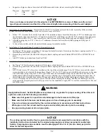
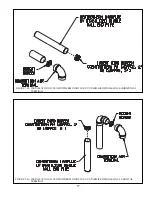
2. Assemble the vent system, starting at the boiler:
a. $#)&#'& && $#\'\ &&
(Figure 7.27). A locking ring in the adaptor prevents the vent pipe from coming out of the adaptor once it is inserted.
} #% #)&' #'& # #&
until it bottoms out.
b. + &#)\&# & _`+ %
"#+#' #*
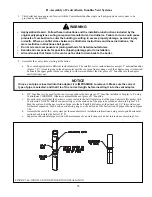
c. For each joint, verify that the gasket is evenly seated in the bell (female) end of the pipe. Lubricate this gasket with
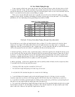
Centrocerin # IACE50. Slide a connector ring over the male end of the pipe to be joined as shown in Figure 7.44.
Push the male end of the next section of pipe into the bell until it bottoms out, then back out 1/4” to provide room
#* ## % %)#&# #' ^ %
7.44.
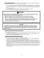
d. ##)#| \ % ## {
sections back towards the boiler 5/8”/ft.
e. Support each horizontal pipe section with a minimum of one wall strap each and at intervals not exceeding 39in.
"&
0
"B+>-?(((*
BBBA)B)((@)-(((
B()*(*(@(ABB)@B,(
-C*?)((@
)A(A-
0
)+A)B,))((-
0
+))BB*BB)B-
0
")A)(***F*-
$!
$ABBB@.%$#)A-.F(
BBB@@*AB-
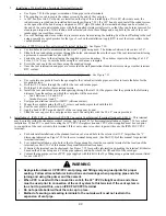
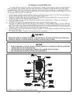
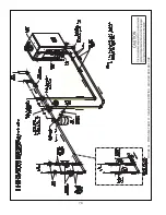
FIGURE 7.44: INNOFLUE CONNECTOR RING INSTALLATION
Summary of Contents for PHNTM080
Page 2: ......
Page 9: ...7 Figure 4 1 Minimum Clearances To Combustible Construction...
Page 11: ...9 Figure 5 1 Wall Layout Mounting Hole Location...
Page 12: ...10 Figure 5 2 Boiler Mounting Bracket Installation Boiler Wall Mounting...
Page 39: ...37 FIGURE 7 24 SPLIT VENT SYSTEM FLEX IN ABANDONED MASONRY CHIMNEY VENT OPTIONS 33 38...
Page 63: ...61 This page is intentionally left blank...
Page 68: ...66 FIGURE 9 2 PIPING METHOD 1 NEAR BOILER PIPING HEATING ONLY...
Page 72: ...70 FIGURE 9 6 PIPING METHOD 1 NEAR BOILER PIPING SHADED BOILER LOOP...
Page 82: ...80 FIGURE 10 4 PROPER INSTALLATION OF HEADER SENSOR...
Page 84: ...82 FIGURE 10 6 INTERNAL WIRING CONNECTIONS DIAGRAM...
Page 85: ...83...
Page 92: ...90 Lighting and Operating Instructions...
Page 101: ...99 FIGURE 12 5 SETTINGS MENU SEE PART C FOR ADDITIONAL INFORMATION...
Page 113: ...111 FIGURE 13 2 IGNITION ELECTRODE GAP FIGURE 13 3 CONDENSATE TRAP EXPLODED PARTS VIEW...
Page 125: ...123...
Page 127: ...125 40 33 31 27 28 34 35 37 38 32 39 36 29 30 48 Blower Gas Valve Assembly for 80 100 120...
Page 129: ...127...
Page 131: ...129...
Page 132: ...130...
Page 133: ...131...
Page 135: ...133...
Page 137: ...135 140 141 142 143 144 145...


