40
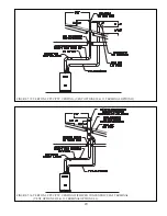
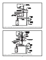
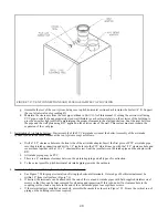
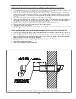
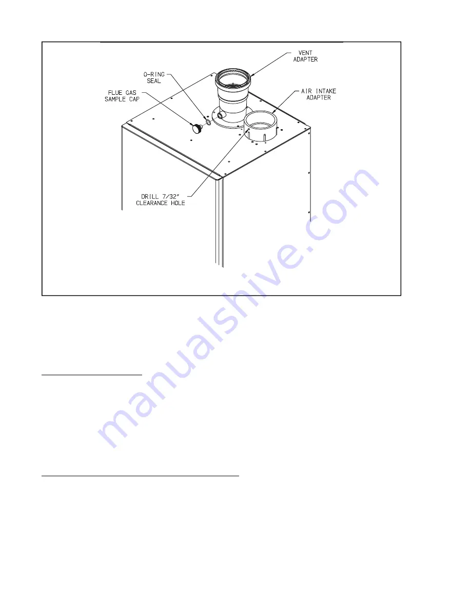
FIGURE 7.27: VENT CONNECTIONS AND FLUE GAS SAMPLE CAP LOCATION
g. Assemble the rest of the vent system, being sure to pitch horizontal sections back towards the boiler 1/4”/ft. Support
the vent at intervals not exceeding 4ft.
h. Maintain the clearances from the vent pipe outlined in Part VII-A of this manual. If exiting the exterior wall using
PVC pipe, use half of an appropriately sized wall thimble (or a sheet metal plate) on the exterior of the building, to
provide a weather tight seal while maintaining the proper clearance in the wall penetration. Seal the joint between
the pipe and the wall plate using RTV applied on the exterior side of the wall. This sealant must not restrain the
expansion of the vent pipe.
3. Installation of Air Intake System - Start assembly of the PVC air intake system at the boiler. Assembly of the air intake
system is done in the same manner as the vent system except as follows:
a. +# # &# &# "
into the air intake connection and drill a 1/8” tap hole into the PVC which lines up with the 7/32” clearance hole and
secure them together with a #10 x 1” sheet metal screw. Seal the joint between the intake pipe and the adaptor with
RTV.
b. All intake piping may be PVC.
c. There is a 0” minimum clearance between the air intake piping and all types of construction.
d. To the extent possible, pitch horizontal air intake piping towards the outdoors.
4. Installation of Horizontal Fitting Terminals (Terminal Option A):
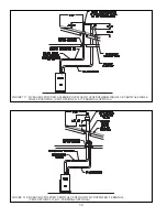
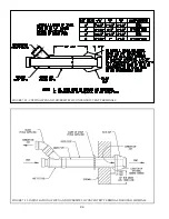
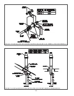
a. See Figure 7.28 for proper orientation of twin pipe horizontal terminals. Outer edge of both terminals must be
within 10” from wall surface. (Figure 7.6)
b. & &\# #&#&#)& ' #& &
screws so that they can be later removed for cleaning and inspection. If this is done, drill a clearance hole in the
coupling or elbow and a tap hole in the end of the vent/intake pipes to accept these screws.
c. If these terminals are installed on snorkels, assemble the snorkels as shown in Figure 7.12. Brace the vertical run of
piping on the building exterior as required.
Summary of Contents for PHNTM080
Page 2: ......
Page 9: ...7 Figure 4 1 Minimum Clearances To Combustible Construction...
Page 11: ...9 Figure 5 1 Wall Layout Mounting Hole Location...
Page 12: ...10 Figure 5 2 Boiler Mounting Bracket Installation Boiler Wall Mounting...
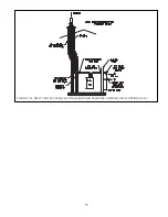
Page 39: ...37 FIGURE 7 24 SPLIT VENT SYSTEM FLEX IN ABANDONED MASONRY CHIMNEY VENT OPTIONS 33 38...
Page 63: ...61 This page is intentionally left blank...
Page 68: ...66 FIGURE 9 2 PIPING METHOD 1 NEAR BOILER PIPING HEATING ONLY...
Page 72: ...70 FIGURE 9 6 PIPING METHOD 1 NEAR BOILER PIPING SHADED BOILER LOOP...
Page 82: ...80 FIGURE 10 4 PROPER INSTALLATION OF HEADER SENSOR...
Page 84: ...82 FIGURE 10 6 INTERNAL WIRING CONNECTIONS DIAGRAM...
Page 85: ...83...
Page 92: ...90 Lighting and Operating Instructions...
Page 101: ...99 FIGURE 12 5 SETTINGS MENU SEE PART C FOR ADDITIONAL INFORMATION...
Page 113: ...111 FIGURE 13 2 IGNITION ELECTRODE GAP FIGURE 13 3 CONDENSATE TRAP EXPLODED PARTS VIEW...
Page 125: ...123...
Page 127: ...125 40 33 31 27 28 34 35 37 38 32 39 36 29 30 48 Blower Gas Valve Assembly for 80 100 120...
Page 129: ...127...
Page 131: ...129...
Page 132: ...130...
Page 133: ...131...
Page 135: ...133...
Page 137: ...135 140 141 142 143 144 145...

