114
a) Soft
Lockout
)# % ##&&\ \
& _#\&& %##`#&*#^
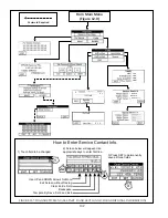
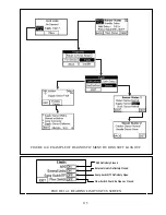
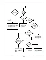
structure during a soft lockout is shown in Figure 14.0
b) Hard
Lockout
#&)# % ##&~# #
been manually reset. This can either be done at the boiler control itself or on the hard lockout screen. An example of the
Fault Menu structure during a hard lockout is shown in Figure 14.2.
A hard lockout closes the alarm contact connections on the low voltage PCB.
c) Sensors
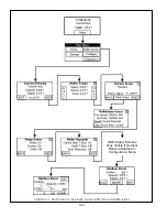
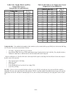
- The Sensor Screens show the status of all sensors. Possible states of the sensors include:
+
None
- The boiler control (R7910B) is not looking for an input from this sensor
+
Normal
- The sensor is working normally
+
Shorted
- There is a short between the boiler control (R7910B) and the sensor or the sensor is defective
+
Open
- There is a break in the wiring between the boiler control (R7910B) and the sensor or the sensor is defective
+
Out of Range
- The sensor is defective or is being subjected to electrical noise.
+
Unreliable
- The sensor is defective or is being subjected to electrical noise.
d) Limit
Status
- The Limit Status Screen shows the status of all safety limits. Each of these limits is either shown as being
ON or OFF. It is important to remember that since all of limits are wired in series, any limit which is in the OFF state
will cause all limits “downstream” of it to also appear on this screen as being OFF, regardless of whether or not they
actually are. The limits are wired in the following order (also see Figure 10.5):
1. External Limits, including LWCO if used.
2. Air Proving Switch (APS)
3. Sump Pressure Switch
4. Flow
Switch
Therefore, in the example shown in Figure 14.1, the Auxiliary limit is known to be closed, the LWCO is known to be
open, and the High Limit and Air Pressure switches could be either open or closed.
B. Troubleshooting when the Display is Blank
#'# ^ %#'##& &
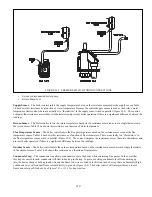
C. Operation and Troubleshooting of Boiler Controls Other than the Sola
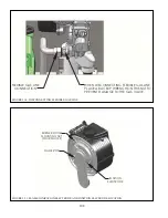
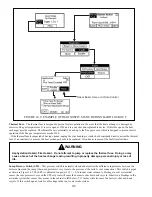
For the location of the controls described below, see Figure 14.4.
Fuses
– This boiler is equipped with two 5 x 20mm fuses:
Q
Pump Fuse
– This fuse protects the relay contacts in the boiler control from excessive current draw caused by an
oversized or seized pump. The fuse supplied with the boiler is a 6.3A, slow blow type. A replacement fuse is supplied
with the boiler. If this fuse blows, look for a seized pump, a short circuit in the pump wiring, or an oversized DHW or
system pump. When a Taco 0013 is supplied for the boiler pump, the total draw of the DHW and system pumps cannot
exceed
4.3A.
Q
24V Fuse
– This fuse protects the transformer from excessive draw and is a 1.6A slow blow type. If this fuse blows, look
# #+' % %# %& &' %_##'
touching a pipe) will cause this fuse to blow. A replacement fuse is supplied with the boiler
Summary of Contents for PHNTM080
Page 2: ......
Page 9: ...7 Figure 4 1 Minimum Clearances To Combustible Construction...
Page 11: ...9 Figure 5 1 Wall Layout Mounting Hole Location...
Page 12: ...10 Figure 5 2 Boiler Mounting Bracket Installation Boiler Wall Mounting...
Page 39: ...37 FIGURE 7 24 SPLIT VENT SYSTEM FLEX IN ABANDONED MASONRY CHIMNEY VENT OPTIONS 33 38...
Page 63: ...61 This page is intentionally left blank...
Page 68: ...66 FIGURE 9 2 PIPING METHOD 1 NEAR BOILER PIPING HEATING ONLY...
Page 72: ...70 FIGURE 9 6 PIPING METHOD 1 NEAR BOILER PIPING SHADED BOILER LOOP...
Page 82: ...80 FIGURE 10 4 PROPER INSTALLATION OF HEADER SENSOR...
Page 84: ...82 FIGURE 10 6 INTERNAL WIRING CONNECTIONS DIAGRAM...
Page 85: ...83...
Page 92: ...90 Lighting and Operating Instructions...
Page 101: ...99 FIGURE 12 5 SETTINGS MENU SEE PART C FOR ADDITIONAL INFORMATION...
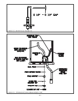
Page 113: ...111 FIGURE 13 2 IGNITION ELECTRODE GAP FIGURE 13 3 CONDENSATE TRAP EXPLODED PARTS VIEW...
Page 125: ...123...
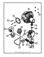
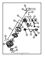
Page 127: ...125 40 33 31 27 28 34 35 37 38 32 39 36 29 30 48 Blower Gas Valve Assembly for 80 100 120...
Page 129: ...127...
Page 131: ...129...
Page 132: ...130...
Page 133: ...131...
Page 135: ...133...
Page 137: ...135 140 141 142 143 144 145...

