101
D. Enter Service Contact Information
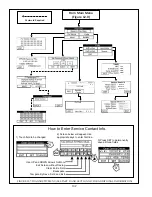
If desired, the technician can enter contact information so that the owner knows who to contact for future service. To do this:
1) From the Main Menu, press the DIAGNOSTICS button.
2) From the Diagnostic Menu, press either the INSTALLER or MORE button (only one will be visible depending on whether
you are “logged in”).
a) If prompted for a password, use the “+1” key to raise the password to “005”. Press SUBMIT, then NEXT (if you
accidently scroll past 005, press EXIT to return to the main menu and start over).
b) Review the Warning and press ACCEPT to continue.
3) Press ENTER CONTACT.
4) $##&# ]#&# \#&#' ^ %+' #
&&''&& # %# \# )#
5) Repeat Step 4 for the remaining two lines.
6) Press SET to permanently save all three lines into the memory of the display.
E. Boiler Status Menu
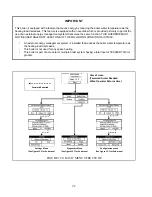
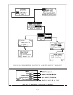
The basic Status Menu is shown in Figure 12.8. It allows the technician to quickly identify how the boiler is currently
% ) # ';
1) Home
Screen
a) Current Demand - The demand to which the boiler is currently responding. If more than one demand is present, the
Current Demands shown will be the one having the highest priority. Typical Current Demands include:
+
No Demand
- The boiler is not receiving a demand of any type.
+
Central Heat
- Boiler is receiving a call for space heat
+
Domestic HW
- Boiler is receiving a call for domestic hot water.
+
Frost Protection
- The boiler supply, or header temperature fell below 45°F and the boiler is responding to prevent
freeze damage to itself.
+
Off on Warm Weather
$#''##&' #& #"% &
the outside air temperature has exceeded the setting at which this function causes the boiler to ignore calls for space
heating.
+
Other Current Demands
, such as “Lead-Lag”, are possible but should never be seen in the applications covered by
this manual.
b) Active
Fault_) '## `)# & ' ## #
system. Touching this indicator takes the users to the Diagnostic Menu. See Section XIV for more information.
c) Supply - Current boiler supply temperature.
Summary of Contents for PHNTM080
Page 2: ......
Page 9: ...7 Figure 4 1 Minimum Clearances To Combustible Construction...
Page 11: ...9 Figure 5 1 Wall Layout Mounting Hole Location...
Page 12: ...10 Figure 5 2 Boiler Mounting Bracket Installation Boiler Wall Mounting...
Page 39: ...37 FIGURE 7 24 SPLIT VENT SYSTEM FLEX IN ABANDONED MASONRY CHIMNEY VENT OPTIONS 33 38...
Page 63: ...61 This page is intentionally left blank...
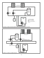
Page 68: ...66 FIGURE 9 2 PIPING METHOD 1 NEAR BOILER PIPING HEATING ONLY...
Page 72: ...70 FIGURE 9 6 PIPING METHOD 1 NEAR BOILER PIPING SHADED BOILER LOOP...
Page 82: ...80 FIGURE 10 4 PROPER INSTALLATION OF HEADER SENSOR...
Page 84: ...82 FIGURE 10 6 INTERNAL WIRING CONNECTIONS DIAGRAM...
Page 85: ...83...
Page 92: ...90 Lighting and Operating Instructions...
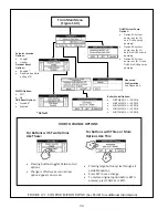
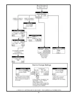
Page 101: ...99 FIGURE 12 5 SETTINGS MENU SEE PART C FOR ADDITIONAL INFORMATION...
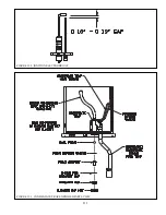
Page 113: ...111 FIGURE 13 2 IGNITION ELECTRODE GAP FIGURE 13 3 CONDENSATE TRAP EXPLODED PARTS VIEW...
Page 125: ...123...
Page 127: ...125 40 33 31 27 28 34 35 37 38 32 39 36 29 30 48 Blower Gas Valve Assembly for 80 100 120...
Page 129: ...127...
Page 131: ...129...
Page 132: ...130...
Page 133: ...131...
Page 135: ...133...
Page 137: ...135 140 141 142 143 144 145...

