103
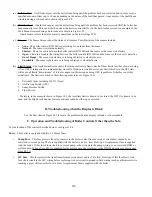
2) Current Priority Screen:
a) Current
Demand
- The demand to which the boiler is currently responding. If more than one demand is present, it is the
#) %## %# )& &! "&
b) Setpoint
- The temperature that the boiler is currently trying to achieve.
c) Supply (or Header) Temperature
- The actual water temperature at the current setpoint location (either the boiler
#&\&& %#&&&'# '& #"% `
d) Setpoint
Source
- Should always read “Local S.P.” in the applications covered by this manual.
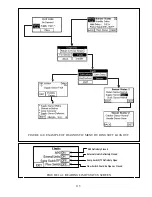
3) Boiler
Temperatures
Screen:
a) Supply
- Current water temperature at boiler supply sensor.
b) Return
- Current water temperature at boiler return sensor.
c) Stack
"% )
d) Header
- Current header sensor temperature. This temperature will only be visible if the header was selected as the
#"%
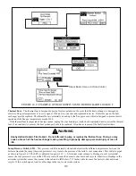
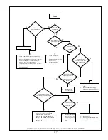
4) Burner Status Screen:
a) Burner
Status
- Indicates what the burner system is currently doing. Typical Burner Status include:
+
Standby -
Burner is not needed because there is no call for heat or the target temperature has been reached.
+
Standby Delay
- Burner is needed, but is being temporarily held off (generally due to a soft lockout - see
Diagnostics section).
+
Safe Start-up
" # % % % (
+
Drive Purge
- Waiting for blower to reach pre-purge speed.
+
Prepurge
' %#' &%%# #_`
+
Drive Light-off
- Waiting for blower to prove that it is at the proper ignition fan speed.
+
Pre-ignition test
- Test the safety relay and verify that downstream contacts are off.
+
Pre-ignition
% { % ' #%))## %
+
Direct ignition
] ## % % {&\#%))&##~
for ignition period is
4s
.
+
Running
%
+
Post-Purge
- Blower is running after the burner shuts off to clear the combustion chamber of residual gasses. Post
purge time is 30s.
+
Lockout
- Boiler is in a hard lockout (see Diagnostic Section).
b) Active
Fault
_) '## `)# & ' ## #
Touching this indicator takes the user to the Diagnostic Menu. See Section XIV for more information.
c) Hold Delay (Visible only during soft lockout)
- Indicates remaining time before next ignition sequence.
d) Flame
Signal
& #%## % "
Summary of Contents for PHNTM080
Page 2: ......
Page 9: ...7 Figure 4 1 Minimum Clearances To Combustible Construction...
Page 11: ...9 Figure 5 1 Wall Layout Mounting Hole Location...
Page 12: ...10 Figure 5 2 Boiler Mounting Bracket Installation Boiler Wall Mounting...
Page 39: ...37 FIGURE 7 24 SPLIT VENT SYSTEM FLEX IN ABANDONED MASONRY CHIMNEY VENT OPTIONS 33 38...
Page 63: ...61 This page is intentionally left blank...
Page 68: ...66 FIGURE 9 2 PIPING METHOD 1 NEAR BOILER PIPING HEATING ONLY...
Page 72: ...70 FIGURE 9 6 PIPING METHOD 1 NEAR BOILER PIPING SHADED BOILER LOOP...
Page 82: ...80 FIGURE 10 4 PROPER INSTALLATION OF HEADER SENSOR...
Page 84: ...82 FIGURE 10 6 INTERNAL WIRING CONNECTIONS DIAGRAM...
Page 85: ...83...
Page 92: ...90 Lighting and Operating Instructions...
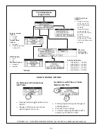
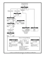
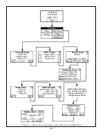
Page 101: ...99 FIGURE 12 5 SETTINGS MENU SEE PART C FOR ADDITIONAL INFORMATION...
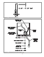
Page 113: ...111 FIGURE 13 2 IGNITION ELECTRODE GAP FIGURE 13 3 CONDENSATE TRAP EXPLODED PARTS VIEW...
Page 125: ...123...
Page 127: ...125 40 33 31 27 28 34 35 37 38 32 39 36 29 30 48 Blower Gas Valve Assembly for 80 100 120...
Page 129: ...127...
Page 131: ...129...
Page 132: ...130...
Page 133: ...131...
Page 135: ...133...
Page 137: ...135 140 141 142 143 144 145...

