93
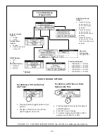
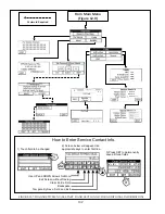
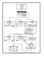
2) Press the CH Button to access central heating options. These include:
a) Setpoint
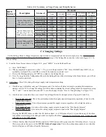
Location& ##' & #%''##
responding to a call for heat. Choices include:
+
Supply
(Generally Recommended) - Boiler attempts to obtain the target temperature during a call for heat at the
supply sensor built into the boiler.
+
Header
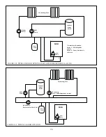
- Boiler attempts to obtain the target temperature during a call for heat at a Honeywell 32003971-003 sensor
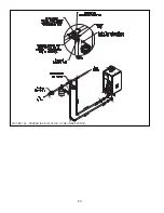
(not included) that must be installed in the header as shown in Figure 10.4 of this manual.
b) Outdoor Reset - Determines whether or not the outdoor reset function is enabled when the boiler is responding to a call
for heat. Choices include:
+
Outdoor Reset Enabled
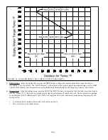
- When the boiler is responding to a call for heat, the target water temperature will adjust
downward (within certain limits) as the outdoor temperature increases. The graph in Figure 12.6 shows how the
target water temperature changes with outdoor temperature. Figure 12.6 shows the default reset curve; the “ends” of
this curve can be changed in the Settings Menu.
+
Outdoor Reset Disabled
]## & %#\#%' *&
%&'##& $# *& #%& # %Outdoor
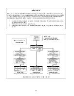
reset function should not be disabled unless at least one of the conditions listed in the “IMPORTANT” box on page
92 is met.
c) If outdoor reset is enabled, press the NEXT key to access two more options related to outdoor reset only. Otherwise,
#$#"% &
d) Warm Weather Shutdown (WWSD) - Determines how the boiler responds to a call from the heating thermostat if the
outdoor temperature is “warm”.
+
WWSD Disabled
- The boiler will always respond to a call for heat regardless of the outdoor temperature.
+
WWSD Enabled
- When the outdoor temperature is above the WWSD Outdoor Temperature setting, the boiler will
ignore a call for space heat (CH) from the thermostat.
e) ODR Boost - Determines if the boiler automatically increases the target temperature above that determined by the reset
curve when it encounters a long call for space heat:
+
ODR Boost Disabled
(Generally Recommended) - When responding to a call for heat, the target water temperature
is determined solely by the outdoor temperature.
+
ODR Boost Enabled
]##\#%' & &#
curve. If the call for heat lasts for 30 minutes, this target temperature is increased by 10°F. The target temperature is
then increased in 10°F increments at 30 minute intervals until one of the following happens:
*
The call for heat ends.
*
The target water temperature is at the top of the reset curve (180°F in the example shown in Figure 12.6)
f) $#"%
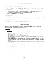
3) If this boiler is installed with an indirect water heater which sends a DHW demand directly to the boiler, press the DHW
#"% %#&!] # # \
the indirect water heater is controlled by an external zoning panel, skip to Step 4.
$## !]% ## & &'& {& $+
In all three cases, this boiler is intended to accept a DHW demand generated by a thermostat mounted in the indirect water
heater, such as a Honeywell L4006A or L4080B, with this device set to the desired potable water temperature. The “DHW
target temperature” is therefore the boiler supply temperature required during a call for DHW.
Summary of Contents for PHNTM080
Page 2: ......
Page 9: ...7 Figure 4 1 Minimum Clearances To Combustible Construction...
Page 11: ...9 Figure 5 1 Wall Layout Mounting Hole Location...
Page 12: ...10 Figure 5 2 Boiler Mounting Bracket Installation Boiler Wall Mounting...
Page 39: ...37 FIGURE 7 24 SPLIT VENT SYSTEM FLEX IN ABANDONED MASONRY CHIMNEY VENT OPTIONS 33 38...
Page 63: ...61 This page is intentionally left blank...
Page 68: ...66 FIGURE 9 2 PIPING METHOD 1 NEAR BOILER PIPING HEATING ONLY...
Page 72: ...70 FIGURE 9 6 PIPING METHOD 1 NEAR BOILER PIPING SHADED BOILER LOOP...
Page 82: ...80 FIGURE 10 4 PROPER INSTALLATION OF HEADER SENSOR...
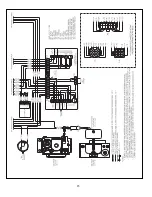
Page 84: ...82 FIGURE 10 6 INTERNAL WIRING CONNECTIONS DIAGRAM...
Page 85: ...83...
Page 92: ...90 Lighting and Operating Instructions...
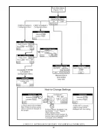
Page 101: ...99 FIGURE 12 5 SETTINGS MENU SEE PART C FOR ADDITIONAL INFORMATION...
Page 113: ...111 FIGURE 13 2 IGNITION ELECTRODE GAP FIGURE 13 3 CONDENSATE TRAP EXPLODED PARTS VIEW...
Page 125: ...123...
Page 127: ...125 40 33 31 27 28 34 35 37 38 32 39 36 29 30 48 Blower Gas Valve Assembly for 80 100 120...
Page 129: ...127...
Page 131: ...129...
Page 132: ...130...
Page 133: ...131...
Page 135: ...133...
Page 137: ...135 140 141 142 143 144 145...

