117
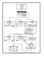
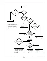
START
Is“ER**”presentin
upperleftcornerof
screen?
x
Consultfactory
Isdisplay
completely
dark?
x
Looseordefectivedisplayharnesswiring
x
Mismatcheddisplayandboilercontrolsoftware
x
UnauthorizedModbusapplication–interrupt
powertotheboiler.Ifnormaldisplayre<
appears,restorefactorysettings.
x
Temporaryerrorcausedbynoise–interrupt
powertotheboilerandseeiferrorclears.
x
Defectivedisplay.
x
Looseordefective
connectionbetweenthe
displayandterminalJ3on
boilercontrol.
x
DefectiveDisplay
Isboilercontrol’s
greenpowerlight
on?
Is120VACpresent
across120VLine
connectionsL&Non
HighVoltagePCB?
x
Openfuseorbreakeratmain
panel.
x
Looseconnectioninwiring
betweenmainpanelandboiler
Is24VACpresent
betweenJ8<1andJ8<2
(BlueandYellow)
terminalsonboiler
control?
x
Defectiveboiler
control(R7910B)
24VACpresentacross
transformersecondary(brown
andpinkwiresatplugL3)?
x
Blown24VfuseonlowvoltagePCB–
lookforshortcircuitin24Vwiring
beforereplacing.Replacewith
5x20mm1.6Aslowblowtypefuse.
x
LooseplugP8(locatedonbacksideof
lowvoltagePCB)
x
LooseplugL3
120VACpresent
acrossblack
andwhitewires
atL2?
x
LooseplugL2
x
LooseplugP3(locatedonback
sideofHighVoltagePCB)
x
Defectivetransformer
–lookforshortcircuit
in24Vwiring.Confirm
installed24Vfuseis
1.6A
Y
N
Y
Y
Y
Y
Y
Y
N
N
N
N
N
N
Isboilerfan
runningathigh
speed?
N
Y
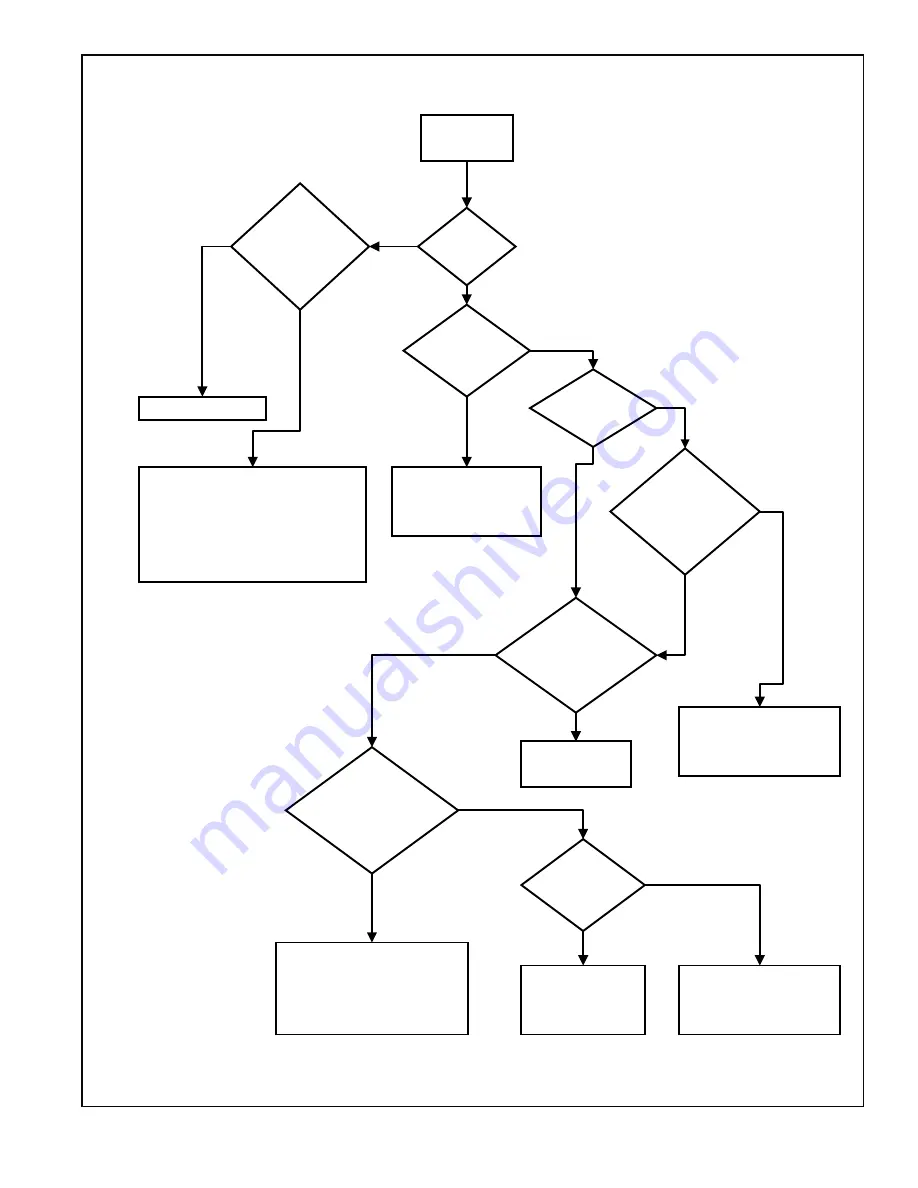
FIGURE 14.3: TROUBLESHOOTING BLANK OR UNREADABLE SCREEN
Summary of Contents for PHNTM080
Page 2: ......
Page 9: ...7 Figure 4 1 Minimum Clearances To Combustible Construction...
Page 11: ...9 Figure 5 1 Wall Layout Mounting Hole Location...
Page 12: ...10 Figure 5 2 Boiler Mounting Bracket Installation Boiler Wall Mounting...
Page 39: ...37 FIGURE 7 24 SPLIT VENT SYSTEM FLEX IN ABANDONED MASONRY CHIMNEY VENT OPTIONS 33 38...
Page 63: ...61 This page is intentionally left blank...
Page 68: ...66 FIGURE 9 2 PIPING METHOD 1 NEAR BOILER PIPING HEATING ONLY...
Page 72: ...70 FIGURE 9 6 PIPING METHOD 1 NEAR BOILER PIPING SHADED BOILER LOOP...
Page 82: ...80 FIGURE 10 4 PROPER INSTALLATION OF HEADER SENSOR...
Page 84: ...82 FIGURE 10 6 INTERNAL WIRING CONNECTIONS DIAGRAM...
Page 85: ...83...
Page 92: ...90 Lighting and Operating Instructions...
Page 101: ...99 FIGURE 12 5 SETTINGS MENU SEE PART C FOR ADDITIONAL INFORMATION...
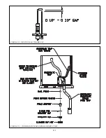
Page 113: ...111 FIGURE 13 2 IGNITION ELECTRODE GAP FIGURE 13 3 CONDENSATE TRAP EXPLODED PARTS VIEW...
Page 125: ...123...
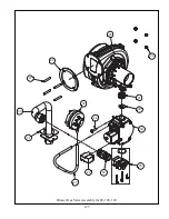
Page 127: ...125 40 33 31 27 28 34 35 37 38 32 39 36 29 30 48 Blower Gas Valve Assembly for 80 100 120...
Page 129: ...127...
Page 131: ...129...
Page 132: ...130...
Page 133: ...131...
Page 135: ...133...
Page 137: ...135 140 141 142 143 144 145...


