91
XII Operation
A. General Information
$# # &!' % & %
) && $' % & #|¦
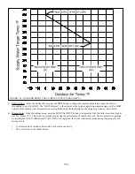
space heating (CH) and one for domestic hot water (DHW) production. If an outdoor temperature sensor is connected to the
boiler, and enabled, the space heating supply set point will automatically shift downward as the outdoor temperature increases.
For more information on this feature see the discussion on boiler water reset below.
The control modulates the boiler input by varying the fan speed. As the fan speed increases, so does the amount of gas drawn
into the blower. As a result, a fairly constant air-fuel ratio is maintained across all inputs. The control determines the input
needed by looking at both current and recent differences between the supply temperature and the set point temperature. As the
supply temperature approaches the set point temperature, the fan will slow down and the input will drop. The minimum input is
approximately 1/5 of maximum input.
$# &&& \#& #
R7910B. The R7910B uses inputs from all of these controls to either shut down the boiler when an unsafe condition exists or, in
some cases, to correct the problem.
Finally, the basic boiler control manages up to three pumps:
Q
Boiler Loop Pump (built into boiler)
Q
DHW pump
Q
System pump
Refer to the Piping Section for the location of these pumps
The touch screen display on this boiler has three basic functions:
1) To allow the professional HVAC technician to set-up this boiler so that it will work properly in the system to which it is
connected.
2) To indicate the current status of the boiler and to provide information that will assist the professional HVAC technician in
solving problems with the boiler and/or system.
3) To advise the homeowner if there is a problem which requires professional service.
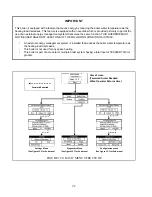
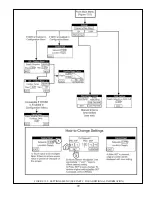
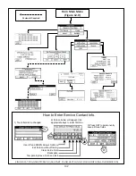
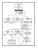
A map of the basic menu structure is shown in Figure 12.0. In order to prevent unauthorized or accidental adjustments, access
to menus, which change settings and boiler operation, is password protected. In general, if a menu is not touched for 255 seconds,
the display backs up to the previous menu. Once the Home Screen is returned to, the password must be reentered in order to
regain access to protected menus (this feature prevents the boiler from being permanently left in operation without password
protection).
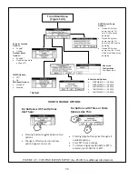
'& &
#"% ) &# ' # #'# # &On a
' %# \#%# %#%'. A map
#"% #' %+$%# ;
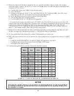
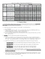
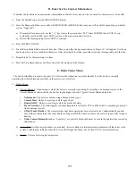
1) From the Home Screen (shown in Figure 12.0) , press “MENU” to enter the Main Menu:
a) Press
“CONFIGURE”
b) When prompted for a password, use the “+1” key to raise the password to “005”. Press SUBMIT, then NEXT (if you
accidently scroll past 005, press EXIT to return to the main menu and start over).
c) ) '#] %&""$ #"%
Summary of Contents for PHNTM080
Page 2: ......
Page 9: ...7 Figure 4 1 Minimum Clearances To Combustible Construction...
Page 11: ...9 Figure 5 1 Wall Layout Mounting Hole Location...
Page 12: ...10 Figure 5 2 Boiler Mounting Bracket Installation Boiler Wall Mounting...
Page 39: ...37 FIGURE 7 24 SPLIT VENT SYSTEM FLEX IN ABANDONED MASONRY CHIMNEY VENT OPTIONS 33 38...
Page 63: ...61 This page is intentionally left blank...
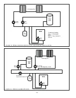
Page 68: ...66 FIGURE 9 2 PIPING METHOD 1 NEAR BOILER PIPING HEATING ONLY...
Page 72: ...70 FIGURE 9 6 PIPING METHOD 1 NEAR BOILER PIPING SHADED BOILER LOOP...
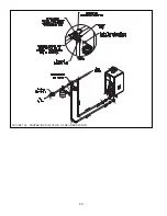
Page 82: ...80 FIGURE 10 4 PROPER INSTALLATION OF HEADER SENSOR...
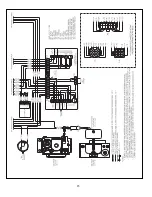
Page 84: ...82 FIGURE 10 6 INTERNAL WIRING CONNECTIONS DIAGRAM...
Page 85: ...83...
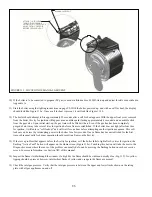
Page 92: ...90 Lighting and Operating Instructions...
Page 101: ...99 FIGURE 12 5 SETTINGS MENU SEE PART C FOR ADDITIONAL INFORMATION...
Page 113: ...111 FIGURE 13 2 IGNITION ELECTRODE GAP FIGURE 13 3 CONDENSATE TRAP EXPLODED PARTS VIEW...
Page 125: ...123...
Page 127: ...125 40 33 31 27 28 34 35 37 38 32 39 36 29 30 48 Blower Gas Valve Assembly for 80 100 120...
Page 129: ...127...
Page 131: ...129...
Page 132: ...130...
Page 133: ...131...
Page 135: ...133...
Page 137: ...135 140 141 142 143 144 145...

