62
VIII Gas Piping
%# {&& )&(%# #
pressure between the minimum and maximum values shown in Table 8.2. When sizing, also consider other existing
and expected future gas utilization equipment (i.e. water heater, cooking equipment). For more information on gas line
sizing, consult the utility or the
National Fuel Gas Code,
NFPA54/ANSI Z223.1, and/or CAN/CSA B149.1
Natural
Gas and Propane Installation Code.
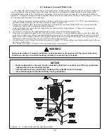
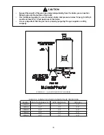
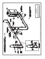
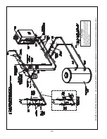
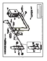
Figure 8.1 shows typical gas piping connection to the boiler. A sediment trap must be installed upstream of all gas
controls. Install the factory provided manual shut-off valve outside the jacket with a ground joint union as shown.
All above ground gas piping upstream from manual shut-off valve must be electrically continuous and bonded to a
grounding electrode. Refer to
National Electrical Code,
NFPA 70.
The boiler and its gas connection must be leak tested before placing the boiler in operation. When doing this, the boiler
and its individual shut-off must be disconnected from the rest of the system during any pressure testing of that system
at pressures in excess of 1/2 psi (3.5kPa). When pressure testing the gas system at pressures of 1/2 psi (3.5kPa) or
less, isolate the boiler from the gas supply system by closing its individual manual shut-off valve. Locate leaks using
approved combustible gas non-corrosive leak detector solution.
"&
+B>-(BBBB(BB*)()BBB
FC))*-
0
(BB*))(**((BA
*BB-
0
"?(BB*(FBB>B
-
0
')B()B*?D( B()-((BB
)B()(FC))*-
0
B(*A4<:BI9-;F%JB((D(-
((BB-
0
>((*I!J(BBB))>C?
-
"&
+B>-()@@BC)(F
F-
"&
B(*(*A4<:BI9-;F%J@B((
D(-'()(BBB)((
B-!()(**BB(B(B(
)BB-(@?)(
D(-(()((<(BB(
D(B)-
Summary of Contents for PHNTM080
Page 2: ......
Page 9: ...7 Figure 4 1 Minimum Clearances To Combustible Construction...
Page 11: ...9 Figure 5 1 Wall Layout Mounting Hole Location...
Page 12: ...10 Figure 5 2 Boiler Mounting Bracket Installation Boiler Wall Mounting...
Page 39: ...37 FIGURE 7 24 SPLIT VENT SYSTEM FLEX IN ABANDONED MASONRY CHIMNEY VENT OPTIONS 33 38...
Page 63: ...61 This page is intentionally left blank...
Page 68: ...66 FIGURE 9 2 PIPING METHOD 1 NEAR BOILER PIPING HEATING ONLY...
Page 72: ...70 FIGURE 9 6 PIPING METHOD 1 NEAR BOILER PIPING SHADED BOILER LOOP...
Page 82: ...80 FIGURE 10 4 PROPER INSTALLATION OF HEADER SENSOR...
Page 84: ...82 FIGURE 10 6 INTERNAL WIRING CONNECTIONS DIAGRAM...
Page 85: ...83...
Page 92: ...90 Lighting and Operating Instructions...
Page 101: ...99 FIGURE 12 5 SETTINGS MENU SEE PART C FOR ADDITIONAL INFORMATION...
Page 113: ...111 FIGURE 13 2 IGNITION ELECTRODE GAP FIGURE 13 3 CONDENSATE TRAP EXPLODED PARTS VIEW...
Page 125: ...123...
Page 127: ...125 40 33 31 27 28 34 35 37 38 32 39 36 29 30 48 Blower Gas Valve Assembly for 80 100 120...
Page 129: ...127...
Page 131: ...129...
Page 132: ...130...
Page 133: ...131...
Page 135: ...133...
Page 137: ...135 140 141 142 143 144 145...


