ELECTRICAL COMPONENTS: FE400, KEY-START ENGINE
Starter/Generator (Model G425419)
2006-2010 Turf/Carryall 272/472 and XRT 1200/1200 SE Maintenance and Service Manual
Page 12-5
12
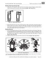
Bearing Removal
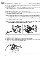
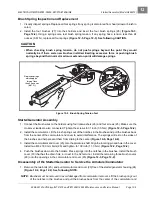
1. Place the wedge attachment tool (CC P/N 1012812) between the bearing and the armature. Make sure
the wedge attachment tool is supporting the inner race of the bearing. If a press is not available, secure
a bearing puller (CC P/N 1012811) to the wedge attachment tool and pull the bearing off of the end of
the armature shaft. Support the armature so that it will not drop when the bearing is removed
2. Discard the bearings.
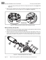
3. Slide the bearing retainer (32) off of the output end of the shaft
Field Coil Removal
1. Remove the retaining nut from each field coil terminal and slide the insulator out of the slots in the hous-
ing. Remove the four pole piece screws from the housing. Remove the four pole pieces from inside the
housing. Remove the field coils from the inside of the housing
See following
NOTE.
NOTE:
Do not remove the insulators or the field coils unless an electrical test indicates that it is necessary
See Test Procedure 8, Section 11, Page 11-19.
Figure 12-8 Bearing Play Inspection
Figure 12-9 Bearing Removal
A
B
USE A
1/2-INCH
SOCKET
OR PIPE
PRESS RAM
USE A 1/2-INCH
SOCKET OR PIPE
SUPPORT
INNER RACE
OF BEARING
PRESS ON
ARMATURE
SHAFT
WEDGE
ATTACHMENT
TOOL
BEARING
PULLER
TOOL
WEDGE
ATTACHMENT
TOOL
NOTE: BEARING IS
SECTIONED FOR CLARITY
Summary of Contents for CARRYALL 272
Page 2: ......
Page 14: ......
Page 18: ...1...
Page 52: ...5...
Page 90: ...6...
Page 110: ...7...
Page 112: ...8...
Page 128: ...10...
Page 170: ...11...
Page 224: ...13...
Page 284: ...16...
Page 302: ...17...
Page 308: ......
Page 309: ...Club Car R NOTES...
Page 310: ...Club Car R NOTES...
Page 311: ......

