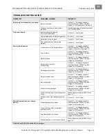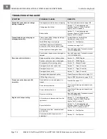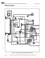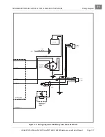
TROUBLESHOOTING AND ELECTRICAL SYSTEM: FE400, KEY-START ENGINE
Test Procedures
2006-2010 Turf/Carryall 272/472 and XRT 1200/1200 SE Maintenance and Service Manual
Page 11-17
11
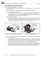
TEST PROCEDURE 6 – SOLENOID
See General Warning, Section 1, Page 1-1.
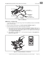
1. Turn the key switch OFF and remove the key. Place the Forward/Reverse handle in the NEUTRAL posi-
tion. Chock the wheels.
2. Disconnect battery and spark plug wire(s).
See Disconnecting The Battery on page 1-3.
3. Remove the electrical component box cover.
4. Check that the wires are connected correctly and are tight. If they are not, rewire or tighten as necessary.
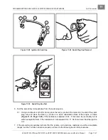
5. Set a multimeter to 200 ohms. Place the red (+) probe on one of the small posts of the solenoid and place
the black (–) probe on the other small post. The reading should be 14 to16 ohms. If the reading is not
within limits, replace the solenoid.
6. Remove the 6 and 18-gauge white wires, and the 16-gauge red wire, from the large post of the solenoid.
Do not allow the wires to touch the frame or other components of the vehicle
.
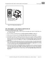
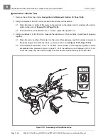
7. Set the multimeter to 200 ohms. Connect the red (+) probe to one of the large posts of the solenoid and
connect the black (–) probe to the other large post
.
8. With the key switch in the OFF position, connect the battery, positive (+) cable first.
9. Place the Forward/Reverse handle in the NEUTRAL position. With the key in the OFF position, the read-
ing on the multimeter should be no continuity. Turn the key switch to the START position and listen for
the solenoid click. While holding the key in the START position, there should be continuity. After the key
is released, it should rotate to the ON position and should be no continuity. If either reading is incorrect,
replace the solenoid.
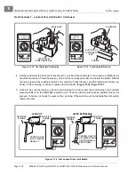
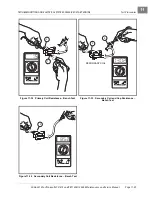
10. With the Forward/Reverse handle still in the NEUTRAL position, set the multimeter to 20 volts DC and
place the red (+) probe on the large post that does
not
have wires connected to it. Place the black (–)
probe on the vehicle frame. Turn key switch to the START position and listen for the solenoid click. While
holding the key in the START position, the meter should read full battery voltage. If the reading is incor-
rect, replace the solenoid
.
11. Disconnect the 6-gauge black wire from the negative post of the battery before reconnecting the wires
to the solenoid.
12. Reconnect the solenoid.
See Solenoid Installation, Section 12, Page 12-25.
See also following
WARNING.
ý
WARNING
• Incorrect wiring could result in severe injury or death.
• Diode and solenoid connections must have correct polarity.
• Keep all persons clear of engine belts when making final connections.
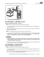
TEST PROCEDURE 7 – LOCKOUT CAM LIMIT SWITCH
See General Warning, Section 1, Page 1-1.
This limit switch is located on the Forward/Reverse switch assembly. A black wire and a green wire are con-
nected to this limit switch.
1. Turn the key switch OFF and remove the key. Place the Forward/Reverse handle in the NEUTRAL posi-
tion. Chock the wheels.
2. Disconnect battery and spark plug wire(s).
See Disconnecting The Battery on page 1-3.
3. Check for proper wiring and tight connections.
Summary of Contents for CARRYALL 272
Page 2: ......
Page 14: ......
Page 18: ...1...
Page 52: ...5...
Page 90: ...6...
Page 110: ...7...
Page 112: ...8...
Page 128: ...10...
Page 170: ...11...
Page 224: ...13...
Page 284: ...16...
Page 302: ...17...
Page 308: ......
Page 309: ...Club Car R NOTES...
Page 310: ...Club Car R NOTES...
Page 311: ......

