TROUBLESHOOTING AND ELECTRICAL SYSTEM: FE400, KEY-START ENGINE
Test Procedures
Page 11-32
2006-2010 Turf/Carryall 272/472 and XRT 1200/1200 SE Maintenance and Service Manual
11
TEST PROCEDURE 21 – OIL LEVEL SENSOR
See General Warning, Section 1, Page 1-1.
NOTE:
Keep the battery connected while performing this test procedure.
1. Turn the key switch OFF and remove the key. Place the Forward/Reverse handle in the NEUTRAL posi-
tion. Chock the wheels.
2. Disconnect battery and spark plug wire(s).
See Disconnecting The Battery on page 1-3.
3. Ensure that the low oil warning light and all connecting wires are functioning correctly.
dure 22 – Oil Warning Light on page 11-32.
4. Drain the engine oil into an approved container and properly dispose of used oil.
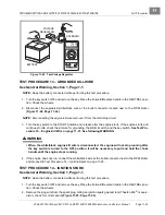
5. Turn the key switch ON, closing the circuit. The oil light should illuminate. If the low oil warning light does
not illuminate, the oil level sensor may need to be replaced. Refer to Test Procedure 22 before replacing
sensor.
See Oil Level Sensor Removal, Section 13, Page 13-5.
6. Fill the engine with new oil and install a new oil filter before returning the vehicle to service.
Oil And Filter Change on page 10-5.
TEST PROCEDURE 22 – OIL WARNING LIGHT
See General Warning, Section 1, Page 1-1.
1. Turn the key switch OFF and remove the key. Place the Forward/Reverse handle in the NEUTRAL posi-
tion. Chock the wheels.
2. Disconnect battery and spark plug wire(s).
See Disconnecting The Battery on page 1-3.
3. Remove the center dash assembly.
See Key Switch Removal, Section 12, Page 12-24.
4. Ensure that the wires are connected correctly and are tight. If they are not, rewire or tighten as necessary.
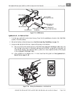
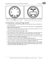
5. Disconnect the yellow wire (to the oil level sensor) from the terminal on the oil light. Using an alligator clip
jumper wire, connect the oil light terminal to the vehicle frame. Connect the red (+) battery cable to the
positive (+) battery post, then attach the black (–) cable to the negative (–) battery post.
6. Turn the key switch to the ON position. The oil light should illuminate. If it does not, check continuity of
the yellow wire that connects the key switch to the oil light through a sonic weld connection within the wire
harness. If there is no continuity in the wire, replace the wire. Then test the key switch.
cedure 4 – Key Switch (Starter Circuit) on page 11-15.
If the yellow wire and the key switch test okay,
then replace the oil light.
TEST PROCEDURE 23 – LOCKOUT CAM
See General Warning, Section 1, Page 1-1.
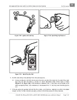
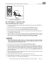
1. Check to be sure the lobes on the cam are pressing the lockout cam limit switch when the Forward/
Reverse shifter is in the NEUTRAL position only. The limit switch should make an audible click as it is
pressed. If it does not, check for wear on the cam lobe. If the cam lobe will not activate the limit switch,
replace the cam.
Summary of Contents for CARRYALL 272
Page 2: ......
Page 14: ......
Page 18: ...1...
Page 52: ...5...
Page 90: ...6...
Page 110: ...7...
Page 112: ...8...
Page 128: ...10...
Page 170: ...11...
Page 224: ...13...
Page 284: ...16...
Page 302: ...17...
Page 308: ......
Page 309: ...Club Car R NOTES...
Page 310: ...Club Car R NOTES...
Page 311: ......

