2006-2010 Turf/Carryall 272/472 and XRT 1200/1200 SE Maintenance and Service Manual
Page 9-1
9
SECTION 9 – REAR SUSPENSION
ý
DANGER
• See General Warning, Section 1, Page 1-1.
ý
WARNING
• See General Warning, Section 1, Page 1-1.
SHOCK ABSORBERS
See General Warning, Section 1, Page 1-1.
SHOCK ABSORBER REMOVAL AND INSPECTION
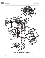
1. Check shock absorbers (1) for damage or fluid leakage around the housing and replace if necessary
.
2. Remove the nut (2), cup washers (3) and rubber bushing (4) from the upper shock absorber stem.
3. Remove lower mounting hardware (6, 7 and 8) on lower mount.
4. Compress the shock absorber to remove it.
SHOCK ABSORBER INSTALLATION
NOTE:
When installing shock absorbers, make sure front shocks have identical part numbers and rear
shocks have identical part numbers.
1. To install, reverse the removal procedure.
2. Tighten nut (2) until rubber bushings (4) expand to the same diameter as the cup washers (3)
.
3. Install mounting hardware and tighten the nut (6) until the rubber bushings (8) expand to the same diam-
eter as the cup washers (7).
MULTI-LEAF SPRINGS
See General Warning, Section 1, Page 1-1.
MULTI-LEAF SPRING REMOVAL
1. Remove shock absorbers.
See Shock Absorber Removal and Inspection on page 9-1.
2. Loosen the lug nuts on wheel(s) to be removed.
3. Chock the front wheels and lift rear of vehicle with a chain hoist or floor jack. If using floor jack, place jack
See WARNING “Lift only one end...” in
Summary of Contents for CARRYALL 272
Page 2: ......
Page 14: ......
Page 18: ...1...
Page 52: ...5...
Page 90: ...6...
Page 110: ...7...
Page 112: ...8...
Page 128: ...10...
Page 170: ...11...
Page 224: ...13...
Page 284: ...16...
Page 302: ...17...
Page 308: ......
Page 309: ...Club Car R NOTES...
Page 310: ...Club Car R NOTES...
Page 311: ......


