STEERING AND FRONT SUSPENSION
Front Suspension Components
Page 7-16
2006-2010 Turf/Carryall 272/472 and XRT 1200/1200 SE Maintenance and Service Manual
7
Kingpin and Steering Spindle Installation, Continued:
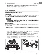
9. Install a new cotter pin (18) and bend it to secure it to the ball joint.
10. Use a grease gun and apply grease to the grease fitting (17) in the A-arm (13)
11. Install the brake cluster.
See Front Brake Cluster Assembly Installation, Section 6, Page 6-17.
12. Install the wheel and tighten the lug nuts, using a crisscross pattern, to 55 ft-lb (74.6 N·m) for steel wheels
or 65 ft-lb (88 N·m) for alloy mag wheels.
13. Repeat steps 1 through 12 for the opposite front wheel if necessary.
14. Check toe-in adjustment and make adjustments if necessary.
See Toe-in Adjustment on page 7-13
A-ARM REMOVAL
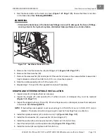
1. Remove the front brake cluster.
See Front Brake Cluster Assembly Removal, Section 6, Page 6-17.
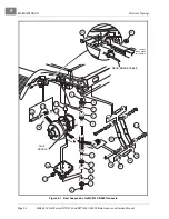
2. Remove cotter pin (18) nut (24) and ball joint from the spindle assembly
3. Remove the nut (22) washer (36) and kingpin (21)
.
4. Remove the thrust washer (32).
5. Remove the wave washer (33) and inspect it. If the washer is broken or has a wave bottom to wave crest
height dimension of less than 0.040 inch (0.10 cm), it must be replaced
6. Slide the spindle assembly (20) off of the A-arm (13).
7. Remove the lower shock absorber mounting bolt (2), nut (3) and steering stop bracket (34).
8. Remove the two bolts (10) two nuts (11) and the A-arm (13) from the suspension mounting plate.
9. Repeat steps 1 through 8 for the opposite front wheel if necessary.
A-ARM INSTALLATION
1. Inspect the bushings (14) and sleeves (15) in the A-arm (13) and replace if necessary
.
2. Inspect the bushings (16 and 18). If worn or damaged, remove and press in new ones.
See following
NOTE
.
NOTE:
If the bushings are replaced, ream new bushings to 0.750-0.752 (3/4-inch) (19.05-19.10 mm) in
diameter. The reamer should be long enough to ream both bushings from one direction.
3. Install the A-arm (13) to the front suspension mounting plate using bolt (10) and nut (11) and tighten to
20 ft-lb (27 N·m)
4. Install the spindle assembly (20) onto the A-arm (13).
5. Install the lower shock absorber mount to the A-arm with bolt (2), nut (3) and steering stop brake hose
bracket (34)
. Align the bracket (34) with the shock absorber and tighten hard-
6. Install the thrust washer (32), wave washer (33) and kingpin (21).
7. Install the washer (36) and a new locknut (22). Tighten to 18 ft-lb (24.4 N·m).
8. Insert the ball joint (23) into the spindle assembly
9. Install the locknut (24) to secure the ball joint to the spindle and tighten to 40 ft-lb (54 N·m).
10. Install a new cotter pin (18) and bend to secure it to the ball joint.
11. Use a grease gun and apply grease to the grease fitting (17) in the A-arm (13)
Summary of Contents for CARRYALL 272
Page 2: ......
Page 14: ......
Page 18: ...1...
Page 52: ...5...
Page 90: ...6...
Page 110: ...7...
Page 112: ...8...
Page 128: ...10...
Page 170: ...11...
Page 224: ...13...
Page 284: ...16...
Page 302: ...17...
Page 308: ......
Page 309: ...Club Car R NOTES...
Page 310: ...Club Car R NOTES...
Page 311: ......

