TROUBLESHOOTING AND ELECTRICAL SYSTEM: FE400, KEY-START ENGINE
Test Procedures
Page 11-16
2006-2010 Turf/Carryall 272/472 and XRT 1200/1200 SE Maintenance and Service Manual
11
TEST PROCEDURE 5 – KEY SWITCH (ACCESSORY TERMINAL)
See General Warning, Section 1, Page 1-1.
1. Turn the key switch OFF and remove the key. Place the Forward/Reverse handle in the NEUTRAL posi-
tion. Chock the wheels.
2. Disconnect battery and spark plug wire(s).
See Disconnecting The Battery on page 1-3.
3. Remove the center dash assembly.
See Key Switch Removal, Section 12, Page 12-24.
4. Ensure that the connector is connected correctly and is tight. If it is not, repair or replace as necessary.
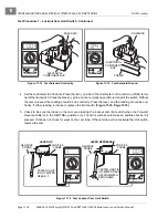
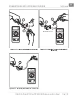
5. Insert the key and turn the switch to the ON position. With the multimeter set to 200 ohms, place the red
(+) probe of the multimeter on the (B) terminal and the black (–) probe on the (L) terminal of the key switch
. The reading should be continuity. If the reading is incorrect, replace the key
See Key Switch Removal, Section 12, Page 12-24.
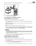
Figure 11-11 Key Switch Test – Accessory Terminal
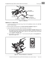
Figure 11-12 Key Switch Test – Starter Circuit
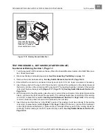
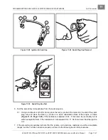
Figure 11-13 Remove Solenoid Wires
Reading with key switch
in the ON position
2m
20
m
200
m
2k
200
200
200
200
20
2
200
m
500
20k
200k
2000
k
1000
OFF
WAVETEK
5XL
V
V
V
A
!
!
COM
200nA
MAX
1000 ---
750V
FUSED
M
B
L
G
S
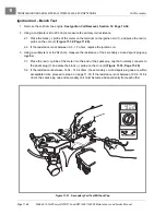
Reading with key switch
in the START position
2m
20
m
200
m
2k
200
200
200
200
20
2
200
m
500
20k
200k
2000
k
1000
OFF
WAVETEK
5XL
V
V
V
A
!
!
COM
200nA
MAX
1000 ---
750V
FUSED
M
B
L
G
S
6-GAUGE WHITE
WIRE ASSEMBLY
16-GAUGE
RED WIRE
ASSEMBLY
18-GAUGE
WHITE WIRE
ASSEMBLY
SOLENOID
ELECTRICAL
COMPONENT
BOX
COVER
Summary of Contents for CARRYALL 272
Page 2: ......
Page 14: ......
Page 18: ...1...
Page 52: ...5...
Page 90: ...6...
Page 110: ...7...
Page 112: ...8...
Page 128: ...10...
Page 170: ...11...
Page 224: ...13...
Page 284: ...16...
Page 302: ...17...
Page 308: ......
Page 309: ...Club Car R NOTES...
Page 310: ...Club Car R NOTES...
Page 311: ......

